32
Sensor Temperature Monitoring Function
The sensor sensing temperature is displayed on the remote controller. This function allows you to make sure whether
the sensor is installed properly.
1) Press + buttons for four seconds or more.
2) Select the Code No. with the TEMP. buttons.
Code No. Location Indication Unit
00
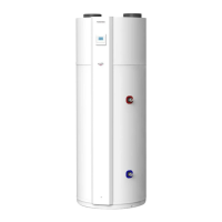
Hydro unit
Control Temperature (Hot water cylinder) °C
01 Control Temperature (Zone1) °C
02 Control Temperature (Zone2) °C
03 Remote controller sensor temperature °C
04 Condensed temperature (TC) °C
06 Water inlet temperature (TWI) °C
07 Water outlet temperature (TWO) °C
08 Water heater outlet temperature (THO) °C
09 Floor inlet temperature (TFI) °C
0A Hot water cylinder temperature sensor (TTW) °C
0B Motorized mixing valve position step
0E Lo pressure (Ps) x 100 MPa
60
Outdoor unit
Heat exchanger temperature (TE) °C
61 Outside air temperature (TO) °C
62 Refrigerant discharge temperature (TD) °C
63 Refrigerant suction temperature (TS) °C
65 Heat sink temperature (THS) °C
6A Current value (in the inverter) A
6D Heat exchanger coil temperature (TL) °C
70 Compressor operating frequency Hz
72 Number of revolutions of outdoor fan (lower) rpm
73 Number of revolutions of outdoor fan (upper) rpm
74 Outdoor PMV position x1/10 pls
F0
Service Data
Micro computer energized accumulation time x100hrs
F1 Hot water compressor ON accumulation time x100hrs
F2 Cooling compressor ON accumulation time x100hrs
F3 Heating compressor ON accumulation time x100hrs
F4 Hydro unit AC pump operation accumulation time x100hrs
F5 Hot water cylinder heater operation accumulation time x100hrs
F6
Hydro unit heater operation accumulation time x100hrs
F7 Booster heater operation accumulation time x100hrs
3) Press button to exit the test mode.
 Loading...