–29–
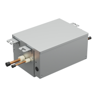
Wiring between indoor (including hot water module) and outdoor
units
A wiring diagram below is an example for connection to SMMS-u series. For connecting to other outdoor unit
series, refer to the Installation Manual attached to the outdoor unit to be connected.
▼Wiring example
U1 U2 SU4U3
Uv Uh
U6L1 L2 L3 N S U
Uc
5 U1 U2 SU4U3
Uv Uh
U6SU
Uc
5
LN
AB
L1 L2 L3 N
LN
AB
LN
AB
LNAB
Uv(U1) Uv(U2)
AB
Uv(U1) Uv(U2)
AB
Uv(U1) Uv(U2)
AB
Uv(U1) Uv(U2)
Outdoor Power supply
380 - 415 V ~, 50 Hz
Circuit breaker,
Power switch
Remote controller
Indoor unit
Outdoor Power supply
380 - 415 V ~, 50 Hz
Remote controller Remote controller
Indoor unit
Circuit breaker Circuit breaker
Outdoor unit
Header outdoor
Outdoor unit
Follower outdoor
Control wiring between outdoor units (Shield wire)
Control wiring between indoor and outdoor units (Shield wire)
Control wiring between indoor units (Shield wire)
Indoor power supply
220 - 240 V ~, 50 Hz
Earth Earth
Earth Earth
Group control
Pull boxPull boxPull box
Earth
terminal
Earth
terminal
S: The ground of a
shielded wire
S: The ground of a shielded wire
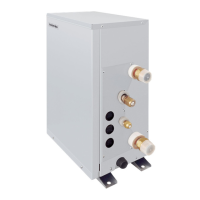
Hot water
module
Hot water
module
Wire connection
• Connect the wires matching the terminal numbers. Incorrect connection causes a trouble.
• Pass the wires through the bushing of wire connection holes of the hot water module.
• Keep a margin (Approx. 100 mm) on a wire to hang down the electrical control box at servicing or other purpose.
• The low-voltage circuit is provided for the remote controller. (Do not connect the high-voltage circuit)
• Remove the front panel of the hot water module by taking off the mounting screws (2 positions).
• Tighten the screws of the terminal block, and fix the wires with cord clamp attached to the electrical control box.
(Do not apply tension to the connecting section of the terminal block.)
• Mount the front panel of the hot water module without pinching wires.
Front
panel
Power supply wiring port
Control wiring port
External signal wiring port
Earth wire
Power supply wire
(Unit: mm)
COM
S2S1 S5S3 S4
CN040
(144'/16'%10641.
ȪȢdzȳဇ
ᲬᲪᲪ᳐ǛҮьƠƳƍƜƱ
Ჾų᳆᳓ųᲬᲬᲪᲧᲬᲮᲪ᳐
#
ϋٳบǓᣐዴဇ
(14+06'470+6
$
4. 50
IC501
RY005
L401
RY006RY007RY008
C170
C150
C140
黒
白
CN030
白赤
CN074
白
橙
橙 赤茶
赤
CN075
茶
FAN
黒
CN102CN101
黒黒
黒
黒黒
TA
CN104
CN041
白
CN083
CN067
黒黒
CN103
黒 白黒黒
CN100
CN022
CN060
7X7
7X7
Side D (Space: 8.5 mm)
Side C (Space: 4 mm)
* Cable clamp can be attached on left side.
Wire
type
Specification
Cable clamping
position
Cabtyre
cable
3-core stranded
wire 2.5 mm²
Side D
Cabtyre
cable
4-core stranded
wire 1.5 mm²
Side C
Earth Screw
Cord clamp
(For power supply
wire)
Power supply wire
Remote controller wire
Control wire
Output signal function wire
57-EN 58-EN
 Loading...


