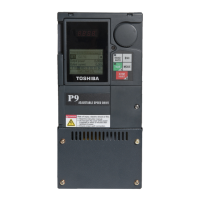
26 P9 ASD Installation and Operation Manual
Typical Connection Diagram
Figure 20. The P9 ASD Typical Connection Diagram.
Note: The AM, FM, and the +SU analog terminals are referenced to CC.
The RR, RX, P24, and the PP analog terminals are referenced to CCA.
The isolated V/I analog terminal references IICC.
Note: When connecting multiple wires to the PA, PB, PC, or PO
terminals, do not connect a solid wire and a stranded wire to
the same terminal.

 Loading...