8
Front panel
Front panel
Screw cap
1
1
Screw
Screw
Screw
*Wiresize28-22AWG
or 0.08-0.32 mm
2
Outerdiameternotover4.7mm,
control wire length 30 m. or less.
2
3
70 mm
5 mm
Notch for wire out
Control wire
Control wire
Terminal
Display unit
1. Remove cover of remote controller by sliding down and take it out.
2. Ifbatteriesareexist,pleasetakethemout.Thecombinationofusing
wire controller and batteries may cause of batteries explosion.
3. Make hole for insert control wire by use screwdriver break the plastic for
coverholeasshownongure4.
4. Insertcontrolwirefromrearsideofremotecontrollerasshownongure5.
5. Fixcontrolwirewhicharrangeasshownongure6 and 7 to terminal
byprovidedscrews(tightenrmlybutnotover0.25N·m(0.03kgf·m)).
6. Set control wire through gutter way at rear side of remote controller as
shownongure8.
7. Fix provided screw (Ø3.1×16L) on the wall to hang remote controller as
shownongure9.
8. Markandarrangeholeforxbelowscrew(Ø3.1×25L)asshownon
gure9.
9. Assembly battery cover which provided with accessory bag then use
providescrew(Ø3.1×25L)toxbatterycovertogetherwithwallas
shownongure0(tightenrmlybutnotover0.15N·m(0.02kgf·m)).
10. Reassembly cover of remote controller.
For remote controller
4 5 6
7
Plastic for cover hole
Control wire
Type A
Type A
Type B
*Wiresize28-22AWG
or 0.08-0.32 mm
2
Outerdiameternotover4.7mm,
control wire length 30 m. or less.
*Terminalsforwiringcanbeeitheronright(typeA)orleft(typeB),dependingonthecontroller
packed in carton.
Control wire
Terminal
30 mm
10 mm
Type B
Control wire
Control wire
Wall
Screw (Ø3.1×16L)
for hang remote
controller
Screw (Ø3.1×25L)
for fix battery cover
Hole for hang
remote controller
Remote controller
Remote controller
8
9
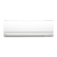
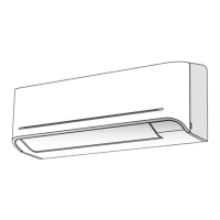
1 Securely remove two screws at the front panel.
Type A: open the air inlet grille upward.
Type B: open two screw caps.
2. Slightly open the lower part of the front panel then pull the upper part of
thefrontpaneltowardyoutoremoveitasshownongure
1
.
3. Arrangethecontrolwireasdetailandspecicationasshownongure2.
4. Securely connect the control wire to terminal of Display unit as shown on
gure3(tightenrmlybutnotover0.12N·m(0.01kgf·m)).
5. Set the control wire out from indoor unit same portion as power supply
andconnectingcableasshownongure
3
. (Notch for wire out)
6. Reassembly the indoor unit by reverse process of 1 to 2.
For indoor unit
How to Connect Remote Controller
for Wire Operation
Indoor unit
Control wire
Remote controller
*Remark : 1. Recommend to use double insulation lead wire for connect
remote control and air conditioner.
2.Forwireoperation,1remotecontrolcancontrolonly1indoorunit.
3.Inwireoperation,remotecontrollerwillreturntoinitial
condition(PRESET,TIMERandCLOCKwillreturntoinitial
condition) when user shutdown power supply of air conditioner.
Battery cover
Screw
0
Type A
Type B
Tighten firmly but not over
0.15N·m(0.02kgf·m)
Screw
1144180111-00_S04_182x257_40p_S_p70_220321.indd 8 22/03/21 8:19:34 AM
 Loading...
