Do you have a question about the Toshiba RAS-10GAH-ES2 and is the answer not in the manual?
| Heating Capacity | 3.2 kW |
|---|---|
| Power Supply | 220-240V, 50Hz |
| Refrigerant | R410A |
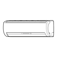
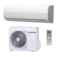
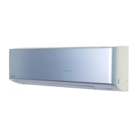
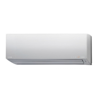
| Indoor Unit Dimensions (WxHxD) | 745 x 250 x 195 mm |
| Outdoor Unit Dimensions (WxHxD) | 681 x 482 x 285 mm |
| Noise Level (Outdoor) | 50 dB(A) |
Details on unit capacity, power source voltage, frequency, and power consumption.
Electrical specs like current, noise levels, and refrigerant details including type and amount.
Electrical schematic for the RAS-10GKHP-ES2 and RAS-10GAH-ES2 models.
Electrical schematic for the RAS-10GKHP-AS2 and RAS-10GAH-AS2 models.
Electrical schematic for the RAS-10GKP-ES2 and RAS-10GA-ES2 models.
Electrical schematic for the RAS-10GKP-AS2 and RAS-10GA-AS2 models.
Diagram illustrating the refrigeration cycle for specific models, including operating conditions.
Diagram illustrating the refrigeration cycle for specific models, including operating conditions.
Block diagram showing control logic for the main unit and remote control.
Cautions regarding R410A refrigerant, impurity prevention, and special tools for installation.
Critical safety warnings, dangers, and precautions for qualified personnel during installation.
Diagram showing placement and connection points for indoor and outdoor units.
Guidelines for proper electrical work, power source connection, and wiring ratings.
Steps for cutting, flaring, and tightening refrigerant pipes for secure connections.
Procedure for removing air from refrigerant lines using a vacuum pump.
Instructions for connecting the power cable to the outdoor unit's terminal block.
Essential checks for power supply, cable connections, and program control issues.
Interpreting lamp blinking patterns for self-diagnosis of unit failures.
Key diagnostic tool using remote control and check codes.
Procedure for entering service mode on the remote control to access diagnostic codes.
Guide to understanding alphanumeric check codes displayed on the remote for fault diagnosis.
Essential diagnostic flowcharts for specific operational failures.
Diagnostic flowchart for troubleshooting when the unit does not turn on at all.
Diagnostic flowchart for cooling models when the unit does not turn on.
Flowchart and wiring checks for troubleshooting power issues after P.C. board replacement.
Flowchart and wiring checks for diagnosing outdoor unit operational failures.
Diagnostic steps for when the outdoor unit fails to operate correctly.
Flowchart for diagnosing issues when only the compressor fails to operate.
Flowchart for diagnosing issues when only the outdoor fan fails to operate.
Flowchart for diagnosing failures specific to the indoor fan operation on heat pump models.
Flowchart for diagnosing failures specific to the indoor fan operation on cooling models.