– 115 –
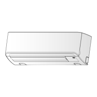
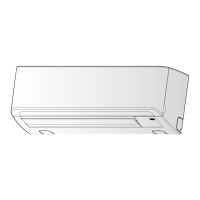
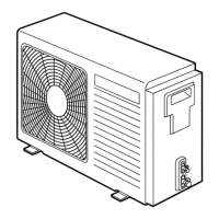
Heat exchanger
Fin guard
Motor base
Discharge port cabinet
Partition plate
Inverter assembly
Piping panel (Rear)
Side cabinet
Valve fixing plate
Valve fixing plate
No.
2
Part name
Discharge
port cabinet
Procedure
1. Detachment
1) Carry out work of 1 of
1
.
2) Remove screws for the discharge port cabinet
and the partition plate.
(ST1T Ø4 × 10, 3 pcs.)
3) Remove screws for the discharge port cabinet
and the bottom plate.
(screw Ø4 × 10, 2 pcs.)
4) Remove screws of the discharge port cabinet
and the motor base. (ST1T Ø4 × 10, 2 pcs.)
5) Remove screws of the discharge port cabinet
and the heat exchanger.
(ST1T Ø4 × 10, 1 pc.)
6) Remove screws of the discharge port cabinet
and the fin guard.
(screw Ø4 × 10, 2 pcs.)
Remarks
1) Carry out work of 1 of
1
.
2) Remove screws which fix the inverter assembly
and the side cabinet. (ST1T Ø4 × 10, 2 pcs.)
3) Remove screws of the side cabinet and the valve
fixing plate. (ST1T Ø4 × 10, 2 pcs.)
4) Remove screws of the side cabinet and the pipe
panel (Rear).
(screw Ø4 × 10, 2 pcs.)
5) Remove screws of the side cabinet and the
bottom plate. (screw Ø4 × 10, 1 pc.)
6) Remove screws of the side cabinet and the heat
exchanger. (screw Ø4 × 10, 3 pcs.)
7) Slide the side cabinet upward and then remove it.
(Hook of inverter)
Side cabinet
3
FILE NO. SVM-13004

 Loading...