FILE NO. SVM-13004
– 67 –
CAUTION
• Wrong wiring may cause a burn-out of some electrical parts.
• Be sure to use the cord clamps attached to the product.
• Do not damage or scratch the conductive core or inner insulator of the
power and inter-connecting wires when peeling them.
• Use the power and Inter-connecting wires with speci ed thicknesses,
speci ed types and protective devices required.
WARNING
1. Using the specifi ed wires, ensure that the wires are connected,
and fi x wires securely so that the external tension to the wires
does not affect the connecting part of the terminals.
Incomplete connection or fi xation may cause a fi re, etc.
2. Be sure to connect the earth wire. (grounding work) Incomplete
grounding may lead to electric shock.
Do not connect ground wires to gas pipes, water pipes, lightning rods
or ground wires for telephone wires.
3. The appliance shall be installed in accordance with national
wiring regulations.
Capacity shortages of the power circuit or an incomplete installation
may cause an electric shock or fi re.
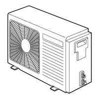
• Remove the panel, and you can see electric parts on the front side.
• A metal pipe can be installed through the hole for wiring. If the hole
size does not t the wiring pipe to be used, drill the hole again to an
appropriate size.
• Be sure to clamp the power wires and indoor/outdoor connecting wires
with a banding band along the connecting pipe so that the wires do not
touch the compressor or discharge pipe.
(The compressor and the discharge pipe become hot.)
Furthermore, be sure to secure these wires with the pipe valve fi xing plate
and cord clamps stored in the electric parts box.
Wiring between indoor unit and outdoor unit
The dashed lines show on-site wiring.
• Connect the indoor/outdoor connecting wires to the identical terminal
numbers on the terminal block of each unit.
Incorrect connection may cause a failure.
For the air conditioner, connect a power wire with the following speci cations.
Model
24 Class
Power suppl y
220-240 V~, 50 Hz
Maximum running current
20A
Installation fuse rating
25 A (all types can be used)
Power wire
H07 RN-F or 60245 IEC 66
(2.5 mm
2
or more)
Indoor/outdoor connecting wires
H07 RN-F or 60245 IEC 66
(1.5 mm
2
or more)
10-4-8. Electrical Work
L
N
1
2
3
1
2
3
Electric parts box
Cord clamp
Pipe hole
Panel
(Main circuit)
Input power
220-240 V~,
50 Hz
(Indoor/outdoor connecting wires)
Outdoor unit Indoor unit
Remote
controller
Earth
Leakage breaker
How to wire
1. Connect the connecting wire to the terminal as identifi ed with their
respective numbers on the terminal block of the indoor and outdoor units.
H07 RN-F or 60245 IEC 66 (1.5 mm
2
or more)
2. When connecting the connecting wire to the outdoor unit terminal, prevent
water from coming into the outdoor unit.
3. Insulate the unsheathed cords (conductors) with electrical insulation tape.
Process them so that they do not touch any electrical or metal parts.
4. For interconnecting wires, do not use a wire joined to another on the way.
Use wires long enough to cover the entire length.
LN
123
Power supply
terminal block
Earth screwEarth screw
Connecting wire Power supply wire
Pipe valve fi xing plate
To Indoor unit
terminal block

 Loading...