Wiremess remote contrommer kit Installation Manuam
HOW TO SETTHE ROOM TEMPERATURE SENSOR
o The room temperature sensors are equipped in the indoor unit and the wireless remote controller.
One of two sensors works.
The room temperature sensor is set to the indoor unit side at the shipment from the factory.
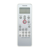
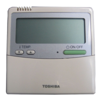
To select the sensor in the remote controller, push the SENSOR button (Right figure) inside of the remote
controller cover and check" _" disappears from LCD.
NOTE
If the room temperature data from the remote controller is not transmitted to the
unit for 10 minutes or more, the sensor at indoor unit side is automatically selected
even if the sensor at the remote controller side is selected.
Fix the remote controller toward the unit as possible.
Sensor
button
HOWTO SETTHE ADDRESS SWITCH
When the multiple signal receiving units are installed in the same room, an address can be set to prevent cross
communication.
When replacing the battery and pushing ACL button, the address of the remote controller becomes [ALL] and the
signal receiving unit is enabled to receive signal regardless of setting of address switch of the operation section.
For selecting of the remote controller address, refer to Owner's Manual.
Change the address of the
signal receiving unit by removing Display of Address Address Address Address
remote controller .....
screws of P.C. board cover of the add .... FILL / 2 5
signal receiving unit.
After then, fix the cover with Address switch _Address switch of 7_' b/, 1 2 3 7_'_ 1 2 3
position of signal signal receiving r_q_
unit can be set .....
screws using a clamp, receiving unit anyposition.
SLIDE SWITCH
Check the slide switch in the battery box of
the remote controller is set to [S] / [A] at
shipment from the factory.
Do not change the setting.
_ elect of operation
mode set to A.
Select of louver
indication set to S.
LEDs on the
signal receiving unit
• : off
_i_ : Blinking
(at intervals of 0.5 sec.)
SELF=DIAGNOSIS TABLE AND
MEASURES
Lamp indication Cause Measures
I_ G _ Power supply is not Check cable
turned on. connection
• • • and correct it.
No indication even if Miscabling between
the remote controller signal receiving unit and
is operated, indoor unit
(_) Q _ Defective connection
,, between signal receiving
Z_;." • • unit and indoor unit
(_ _.) _ Miscabling or defective
• • _. connection between
-_- indoor and outdoor units
• Protective device of Check
++ outdoor unit works, outdoor unit.
Bbinks akematively
• _ _i_ Protective device of Check
...... indoor unit works, indoor unit.
Blinks alternatively
English-5 5
 Loading...