– 18 –
DIP switch DIP switch DIP switch DIP switch
Remote controller
(inside, rear)
Header remote
control/scheduled
timer operation
Header remote
control/timer
operation
Follower remote
control/scheduled
timer operation
Follower remote
control/no timer
function
Multiple wiring diagram
Selecting the operation when the
power is restored after a power outage
How to wire the remote controller
Terminal block
for remote
controller wiring
in indoor unit
Remote controller
(Header)
Terminal block for
remote controller wiring
Earth
Indoor
unit
Remote
controller wire
(procured on site)
Remote controller
(Follower)
(sold
separately)
Remote controller wiring
(procured on site)
Connection diagram
Basic wiring diagram
Remote controller
terminal block
Remote controller
* AWG20 (Use 0.5 mm
2
wire)
* Can not use the closed end
wire joint.
* Use UL wires rated 300 V.
* Terminals A and B are non-polar
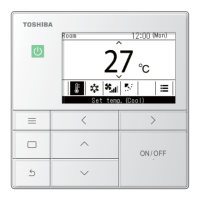
Remote controller test run setup
1. Push and hold the button for 4 seconds or more
unitil "TEST" appears in the LCD display, then press the
button.
• "TEST" appers in LCD display during the test run.
• Temperature adjustment is not possible while "TEST" is
displayd. The test run applies considerable load on the
machine; therefore, it is recommended not to use the
test mode beyond necessity
Follow the steps below to select and set the operation
status of the air conditioner when power is restored after a
power outage has occurred during a scheduled operation.
1. Hold down the + buttons for at least 4 seconds.
(This step can be performed whether the air conditioner
is running or shut down.)
4. Push the button. The setting data is entered
successfully if the display stops blinking and lights up.
2. Push the TEMP. / buttons, and set code No.14.
5. Push the button.
*
00 00
(factory setting):
No settings are sent when the power is restored,
and the scheduled operation is resumed as soon
as the program time is reached after the power has
been restored.
*
00 01
:If there was a program which was to have run
during the power outage, it is resumed in
accordance with what was programmed. If there is
no program, operation resumes in accordance with
what was being performed prior to the power outage.
3. Push the TIME / buttons, and set the setting
data to
00 00
(factory setting) or
00 01
.
2. The test mode should be used in either HEAT or COOL
mode.
NOTE: The outdoor unit will not operate for approx.
3 minutes after power up, or the operation will stop.
3. Be sure the "TEST" indication in the LCD disappeared by
pushing the button agin after exiting the test mode.
(The remote controller has a 60-minute off timer function
to prevent continuous test run)
Type Name : RBC-AMS41E
Part No. : 43166012
Substitution : NO
Type of Remote : Schedule timer
Reference : SX-A5EE
Product used : VRF
Note :
16
120
120
DI
SDI
MiNi-SMMS
SMMS
SHRM
SMMS-i
SHRM-i
OK
OK
OK
OK
OK
OK
OK
Category
4. Schedule Timer

 Loading...