– 31 –
Basic wiring
Wiring Diagram
U1/U3:
U2U4:
C3:
C4:
Auxiliary
Ground for Central control wiring
A1:
A2:
A3:
B1:
B2:
B3:
Input for turning on air conditioners concurrently.
Input for turning off air conditioners concurrently.
Common input for turning air conditioners on or off.
On operation state indicator output.
Alarm indicator output.
Common indicator output.
Power supply ( 50 Hz/60 Hz, 220 . 240 V)
• Power supply wire specification: Cable 3-core,
in conformance with Design 60245 IEC 57.
• Fix the wires with cord clamp.
Central control wiring. (Low voltage)
Terminal for remote monitoring
N
L
B3 B2 B1 A3 A2 A1
U1/U3
U2/U4
C3
C4
CN02
Clamp for electrical wiring
PCB
Connector (CN02)
for weekly timer
(optional)
Earth for
power
wiring
N:
L:
1-1 1-3 1-2 2-1 2-2 2-3 3-1
When connecting a ON-OFF
controller for RAV series
indoor unit (except KRT),
add the "1:1 Model"
connection interface to
indoor unit.
ON-OFF
controller
Refrigerant
system 3 (RAV)
Refrigerant
system 2
(VRF)
Refrigerant
system 1
(VRF)
ON-OFF
controller
When
connecting to
VRF outdoor
units
Central control wiring
Indoor/outdoor unit
connecting wire
When connecting to
MMO indoor units
“1:1 Model”
connection interface
7. ON-OFF Controller
Type Name : TCB-CC163TLE / TCB-CC163TLE2
Part No. : Not assigned
Substitution : TCB-CC163TLE2
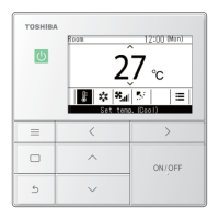
Type of Remote : ON-OFF controller
Reference : NO
Product used : VRF
Note :
NO LONGER AVAILABLE
116
160
148
6
(6)
122
160
148
6
(6)
121
115
69
14
128
80
128
80
36
47
13
Z
DI
SDI
MiNi-SMMS
SMMS
SHRM
SMMS-i
SHRM-i
OK
OK
OK
OK
OK
OK
OK
Category

 Loading...