– 2 –
16
120
4
2.7
120
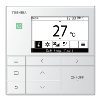
Type Name : RBC-AMT21E
Part No. : 4316V194
Substitution : NO
Type of Remote : Wired
Reference : SX-A3JE
Product used : VRF, Light commercial
Note : *4-way (UT-E series)
* Duct ( BT-E series)
* Under ceiling ( CT-E series)
DI
SDI
MiNi-SMMS
SMMS
SHRM
SMMS-i
SHRM-i
NO
NO
NO
OK
NO
NO
NO
Category
Earth
Remote controller
(Header)
Remote controller
(Follower)
21
(Sold separately)
Terminal block for
remote controller wire
Remote controller wire
(Procured locally)
Indoor
unit
Terminal block for
remote controller
wire in indoor unit
A
B
Approx. 200mm
W: White
B : Black
W
B
Remote controller wire
(Procured locally)
Wire from
remote controller body
Connecting
section
Remote
controller
Non polarity, 2 core wire is used.
Use 0.5mm² to 2mm² wire.
Connection diagram
Basic wiring diagram
How to perform wiring
of the remote controller
Earth Earth Earth Earth
(Sold
separately)
Terminal block
for remote
controller
cable
Remote controller inter-unit
wiring for group control
(Procured locally)
Remote controller
(Follower)
Remote controller
(Header)
Indoor unit
No.1
BA
Indoor unit
No.2
BA
Indoor unit
No.3
BA
Indoor unit
No.N
BA
Remote controller
address
Remote controller
Remote controller
address connector
Master remote controller
Remote controller
check
Secondary
remote
controller
(Max. 2 remote controllers can be set.)
Multiple wiring diagram
Remote controller test run setup
1. When the remote controller is used for the first time, it
will not accept an operation until approximately 5 minutes
after the power supply has been turned on.
This is not a fault, as this time is used to check the setup
of the remote controller.
2. Push the key after [TEST] has been displayed
on the LCD by keeping the button on the remote
controller pressed for 4 seconds or more.
During the test run, [TEST] is displayed on the LCD.
The temperature cannot be controlled if [TEST] is
displayed.
Do not use [TEST] in a case other than a test run,
otherwise an excessive load is applied to the air
conditioner.
3. Use [TEST] in either HEAT, COOL, or FAN operation
modes.
NOTE : The outdoor unit will not operate for approx.
3 minutes after the power supply has been turned
on or theoperation has been stopped.
4. After the test run has finished, push the button again
to check the [TEST] symbol on the LCD has gone off.
(For this remote controller, a release function of 60
minutes is provided to prevent continuous test runs.)

 Loading...