– 43 –
3
1
4
2
1
4
2
1
2
13
ON / OFF
FAN
TEMP.
SWING/FIXTIME
MODE
VENT
UNITSET CL
FILTER
RESET
TEST
TIMER SET
CODE No.
UNIT No.
< RBC-AMT21E > < RBC-AMT31E >
SET
TIME
TIMER SET
TEST
FILTER
RESET
TEMP.
CL
FAN
SAVE
SWING/FIX
VENT
MODE
ON / OFF
UNIT LOUVER
< RBC-AMT32E >
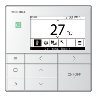
9. Montor Function of Remote Controller Switch
<Produre> (RBC-AMT21E)
1 Push + buttons simultaneously for 4 seconds or more to call up the service monitor mode.
2 Pushing button returns the display to the normal display.
(RBC-AMT31E, RBC-AMT32E)
1 Push
CL
+
TEST
buttons simultaneously for 4 seconds or more to call up the service monitor mode.
The service monitor goes on, and temperature of the item code
0000
0000
00 is firstly displayed.
2 Push the temperature setup / buttons to select the CODE NO. (DN code) to be monitored.
For displayed codes, refer to the table below.
3 Push
UNIT
(
UNIT LOUVER
RBC-AMT32E) button to change the item to one to be monitored.
Then monitor the indoor unit and sensor temperature or operation status in the corresponding
refrigerant line.
4 Pushing
TEST
button returns the display to the normal display.
CODE
No.
00
01
02
03
04
05
08
F2
F3
0A
0B
0C
0D
Data name
Room temp.
(Under control) (Note 1)
Room temp. (Remote controller)
Indoor suction temp. (TA)
Indoor coil temp. (TCJ)
Indoor coil temp. (TC2)
Indoor coil temp. (TC1)
Indoor PMV opening degree
Indoor fan accumulated operation time
Filter sign time
No. of connected indoor units
Total HP of connected indoor units
No. of connected outdoor units
Total HP of connected outdoor units
Unit
˚C
˚C
˚C
˚C
˚C
˚C
pls
h
h
unit
HP
unit
HP
Display
form
×1
×1
×1
×1
×1
×1
× 1/10
× 100
×1
×10
×10
Individual outdoor unit data (Note 3, 4)
CODE
No.
10
11
12
13
14
15
16
17
18
19
1A
1B
1D
1E
1F
Data name
Compressor 1 discharge temp. (Td1)
Compressor 2 discharge temp. (Td2)
High pressure sensor detection pressure (Pd)
Low pressure sensor detection pressure (Ps)
Suction temp. (TS)
Outdoor coil temp. (TE)
Liquid side temp. (TL)
Outside temp. (TO)
Low pressure saturation temp. (TU)
Compressor 1 current (I1)
Compressor 2 current (I2)
PMV1 + 2 opening degree
Compressor 1, 2 ON/OFF
Outdoor fan mode
Outdoor unit HP
Unit
˚C
˚C
MPa
MPa
˚C
˚C
˚C
˚C
˚C
A
A
pls
—
—
HP
Display
form
×1
×1
× 100
× 100
×1
×1
×1
×1
×1
×10
×10
× 1/10
(Note 2)
0to31
×1
Indoor unit dataSystem data
(Note 1) In the group connection, only data of the
header indoor unit isdisplayed.
(Note 2) 01: Only compressor 1 is ON.
10: Only compressor 2 is ON.
11: Both compressor 1 and 2 are ON.
(Note 3) For the CODE No., an example of header unit
is described.
(Note 4) Upper girder of CODE No. indicates the
outdoor unit No.
1: Header unit (A)
2: Followe run it (B)
3: Follower unit (C)
4: Follower unit (D)
(RBC-AMT32E Not used)

 Loading...