– 7 –
Type Name : RBC-AX31U(W)-E
Part No. : Not assigned
Substitution : NO
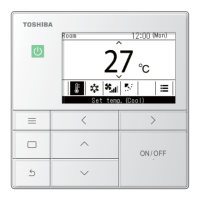
Type of Remote : Wireless remote controller kit
Reference : NO
Product used : Light commercial
Note : *4-way
66.6
66.6
DI
SDI
MiNi-SMMS
SMMS
SHRM
SMMS-i
SHRM-i
OK
OK
OK
OK
OK
OK
OK
Category
Type Name : RBC-AX31U(WS)-E
Part No. : Not assigned
Substitution : NO
Type of Remote : Wireless remote controller kit
Reference : NO
Product used : Light commercial
Note : *4-way
*Color of receiver panel is black
*Refer to Hand Unit and Receiver
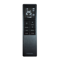
3. WIreless Remote Contoroller
White
Black
white
(Separately sold)
Indoor unit No.1 Indoor unit No.2 Indoor unit No.3 Indoor unit No.4
(Separately sold)
(Separately sold)
Indoor unit
How to wire the signal receiving
Rmote controller
connection
terminal block
Indoor unit remote
contoroller connection
teriminal block
Electric parts box
Signal
receiving
part
Clamping claw
Clampaers
Connect the wires from the signal receiving part to the
remote controller connection terminal block of the indoor
unit. (The terminals are nonpolar.).
• Clamp the redundant portion of the wires with the
clampers in the electric parts box.
Indoor unit
Wireless remote
controller kit * (Header)
* Use 0.5 to 2 mm
2
wires for on-site wiring.
* The total length of wires should be 400m or less.
* Use 0.5 to 2 mm
2
wires for on-site wiring.
* The total length of inter-unit wires should be 200m or less.
Signal
receiving part
Signal
receiving
part
Remote controller wiress
(procured on site)
Remote controller
connection
terminal block
Remote
controller
connection
terminal
block
Remote controller inter-unit
wiress for group control
(Procured on site)
Earth
Earth
Earth Earth Earth
Wired remote
controller * (Follower)
Wireless remote
controller kit * (Header)
Wired remote
controller * (Follower)
Signal receving part
Remote controller test run setup
Perform usual operations using the remote controller to check for
normal operation. A test run can be executed forcibly by using the
following procedure if the room temperature is too high to turn off
the thermostat.
1. Turn off the power of the air conditioner, and remove the screws
to detach the signal receiving part cover.
2. Set bit 1 of DIP switch S003 on the signal receiving part P.C.
board to ON.
3. Attach the signal receiving part to the ceiling panel by reversing
the procedure of removal, and then turn on the power of the air
conditioner.
4. Push [START/STOP] button on the wireless remote controller,
and select COOL or HEAT with [Mode] button.
(Temperature cannot be controlled during a test run.)
5. All LEDs on the signal receiving part flash during a test run.
6. After the test run has been completed, be sure to set bit 1 of DIP
switch S003 to OFF and confirm that the LEDs do not flash.
7. Clamp the wires properly with the clamper secured together with
the signal receiving part cover.
Note1: Use the forced test run only for test run because it overloads
the air conditioner.
Note2: The remote controller is disabled for approx. 1 minute after
power-on, but this is normal. The signal from the remote
controller is received, but the receive data is discarded.
Connection diagram
Connection
• Header and follower indoor units are operable even if they
are attached to any indoor unit.
Controlling one indoor unit by two remote controllers
• Header and follower indoor units are operable even if they
are attached to any indoor unit.
Performing group control of multiple indoor units by
two remote controllers.
(Black type)

 Loading...