108 RemotEye 4 User Manual – 90988-007
FIRMWARE SPECIFICATIONS
Table 12-3 Firmware Specifications
Modbus TCP, Modbus RTU, BACnet/IP, BACnet MS/TP
SNMP over UDP/IP, HTTP over TCP/IP
ARP, RARP, DHCP, DNS, BOOTP, SMTP, SNTP, TFTP,
SSL, SSH, PPP, ICMP, RADIUS
PCB GOLD FINGER (GF1)
NETWORK CONNECTOR (J2)
Table 12-4 Pin-outs for Network RJ-45
RS-232/EMD CABLING KEY (J3)
Table 12-5 Pin-outs for RS-232/EDM RJ-45
Request To Send – RS232 level
Data Terminal Ready – RS232 level
Serial Data Out (to PC) – RS232 level
Data Carrier Detector – RS232 level
Serial Data In (from PC) – RS232 level
Data Set Ready – RS232 level
Clear To Send– RS232 level
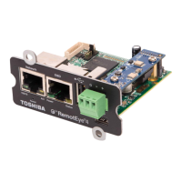
Figure 12-1 PCB Top View/Goldfinger
Goldfinger Pin 1, 2 - VCC/GND Long Pads
Goldfinger Pin 2, 4, 6, 8, 10 - PCB Top Layer
Goldfinger Pin 1, 3, 5, 7, 9 - PCB Bottom Layer
 Loading...