50 RemotEye 4 User Manual – 90988-007
MODBUS RTU OR BACNET MS/TP SETUP
6.3.1 Configure for Modbus RTU
Serial communication protocols require additional configuration with the INTERFACE configuration panel. Ref.
Table 12-6 Pin-outs for RS-485 (Phoenix) Connector
HARDWARE CONNECTIONS:
1. Wire the RemotEye 4 Phoenix connector for the RS-485 Serial port to the serial input cables as follows:
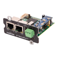
Figure 6-3 RemotEye 4 RS-485 Data and GND Cabling
The RS-485 Signal range is:
Input voltage range: 0 to 5 Volts
Output voltage range: -7 to 12 Volts
SOFTWARE CONFIGURATION:
2. On the home page dashboard, click on the SETTINGS menu at the top of the page. This will bring up the
SETTINGS drop-down menu. (See Figure 6-4.)
3. In the SETTINGS drop-down menu click on “Interface Settings” the selected entry text will turn RED.
3.1. If using RS-485
3.1.1. Under “RS-485 Interface Settings” set RS-485 Interface (Enable/Disable) to “Enabled”, and set
Define RS-485 Interface Protocol to “Modbus”.
3.1.2. Under “RS-232 Interface Settings” set RS-232 Interface (Enable/Disable) to “Disabled”, and set
Define RS-232 Interface Protocol to “Disabled”.
3.2. If using RS-232
3.2.1. Under “RS-232 Interface Settings” set RS-232 Interface (Enable/Disable) to “Enabled”, and set
Define RS-232 Interface Protocol to “Modbus”.
3.2.2. Under “RS-485 Interface Settings” set RS-485 Interface (Enable/Disable) to “Disabled”, and set
Define RS-485 Interface Protocol to “Disabled”.
Figure 6-4 Interface Settings for Modbus RTU
 Loading...