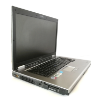
Do you have a question about the Toshiba Satellite Pro S300 and is the answer not in the manual?
| Tjunction | 100 °C |
|---|---|
| Processor cache | 2 MB |
| Processor cores | 2 |
| System bus rate | - GT/s |
| Processor family | Intel® Core™2 Duo |
| Processor socket | Socket 478 |
| Processor codename | Penryn |
| Processing Die size | 107 mm² |
| Processor frequency | 2.1 GHz |
| Processor lithography | 45 nm |
| Processor manufacturer | Intel |
| Processor front side bus | - MHz |
| Processor operating modes | 32-bit, 64-bit |
| ECC supported by processor | No |
| Thermal Design Power (TDP) | 35 W |
| Number of Processing Die Transistors | 410 M |
| Motherboard chipset | Intel® GM45 Express |
| Optical drive type | DVD Super Multi DL |
| Card reader integrated | Yes |
| Total storage capacity | 250 GB |
| Compatible memory cards | SD, xD |
| Display surface | Matt |
| Display diagonal | 15.4 \ |
| Display resolution | 1280 x 800 pixels |
| Internal memory | 2 GB |
| Memory clock speed | 800 MHz |
| Internal memory type | DDR2-SDRAM |
| Maximum internal memory | 8 GB |
| Maximum graphics card memory | 1.34 GB |
| CD-R read speed | 24 x |
| DVD+R read speed | 8 x |
| CD-RW write speed | 4 x |
| DVD+R Double Layer write speed | 6 x |
| Front camera resolution (numeric) | 1.3 MP |
| Modem speed | 56 Kbit/s |
| Bluetooth version | 2.1+EDR |
| Operating system installed | Windows Vista Business |
| Optional operating system supplied | Windows XP Professional |
| Battery life (max) | 4.33 h |
| Charging port type | DC-in jack |
| USB 2.0 ports quantity | 4 |
| Parallel ports quantity | 0 |
| CardBus PCMCIA slot type | Type II |
| Cable lock slot type | Kensington |
| Pointing device | Touchpad |
| Keyboard number of keys | 87 |
| Processor ARK ID | 42841 |
| Depth | 265 mm |
|---|---|
| Width | 361.3 mm |
| Weight | 2800 g |
| Height (rear) | 39.1 mm |
| Height (front) | 37.1 mm |
Details DANGER, WARNING, CAUTION, and NOTE messages for safety.
Details computer features like microprocessor, memory, chipset, and VGA controller.
Provides a block diagram illustrating system unit components and their connections.
Describes the specifications and functionality of the USB external floppy disk drive.
Details the specifications for the 2.5-inch Hard Disk Drive.
Describes various types of Optical Disk Drives supported by the system.
Provides details about the keyboard layout and connection.
Details specifications for the TFT Color Display and LCD Module.
Explains the functions and output ratings of the power supply.
Describes the main and RTC battery types and charging control.
Lists the specifications for the AC adapter.
Defines Field Replaceable Units (FRUs) and outlines troubleshooting procedures.
Provides a flowchart to guide troubleshooting steps for various issues.
Details procedures for diagnosing and resolving power supply issues.
Guides on determining if the system board is malfunctioning.
Provides troubleshooting steps for the USB Floppy Disk Drive.
Outlines procedures for troubleshooting the 2.5-inch Hard Disk Drive.
Provides steps for diagnosing and resolving keyboard issues.
Guides on troubleshooting the touch pad functionality.
Details procedures for diagnosing and resolving display issues.
Outlines steps for troubleshooting the optical disk drive.
Provides procedures for diagnosing and resolving modem issues.
Guides on troubleshooting the Local Area Network (LAN) connection.
Details steps for troubleshooting the Wireless LAN functionality.
Outlines procedures for diagnosing and resolving Bluetooth issues.
Provides steps for troubleshooting the computer's sound system.
Guides on troubleshooting the bridge media slot functionality.
Details troubleshooting for the PCI ExpressCard slot.
Provides steps for diagnosing and resolving fingerprint sensor issues.
Outlines procedures for troubleshooting the web camera.
Guides on troubleshooting Intel Turbo Memory functionality.
Explains how to use diagnostic test programs for hardware modules.
Provides steps to start and execute various diagnostic tests.
Details how to set hardware configuration and manage DMI information.
Describes the procedure and content of the heatrun test.
Lists the names of subtests available in the diagnostic test menu.
Explains the execution of system tests including ROM checksum and fan control.
Details procedures for testing conventional, protected mode, and cache memory.
Describes how to perform keyboard tests, including pressed key display.
Explains tests for VRAM, VGA gradation, and LCD gradation.
Details procedures for testing floppy disk drive functionality.
Notes that the printer test is not supported for this model.
Describes tests for asynchronous communication via FIR/SIR or wraparound.
Outlines procedures for testing hard disk drive functionality.
Explains tests for the real-time clock and backup memory.
Describes tests for the Numeric Data Processor (NDP) functions.
Details tests for expansion interfaces like PCMCIA and RGB monitor ID.
Explains tests for CD-ROM and DVD-ROM drives.
Lists and explains various error codes and their status names.
Provides detailed status information for hard disk test errors.
Tests unique system functions like keyboard, touch pad, and LEDs.
Describes the procedure for cleaning floppy disk drive heads.
Explains how to log and store error information.
Executes a sequence of system, memory, display, and disk tests.
Provides utilities for formatting, copying, dumping, and reading FDD/HDD.
Displays current system configuration information.
Describes how to check Atheros wireless LAN card type and antenna connection.
Details the setup for testing Intel-made wireless LAN cards with a reference PC.
Explains how to perform wireless LAN transmitting-receiving test on the DUT.
Describes how to test sound functionality using Windows OS.
Provides instructions for testing 3G functionality.
Explains how to access and configure system setup options.
Introduces FRU replacement procedures and provides a chart for FRU removal order.
Lists critical safety instructions before disassembling the computer.
Provides important notes and environmental considerations before starting work.
Describes the four main types of cable connectors used.
Offers general points to follow when reassembling the computer.
Lists essential tools and equipment required for disassembly and assembly.
Provides specifications for screw tightening torque values.
Details the procedure for removing and installing the battery pack.
Provides steps for removing and installing the SIM card.
Covers the removal and installation of PC cards, Bridge media, and Smart cards.
Details the procedure for removing and installing the memory module.
Describes the removal and installation of the fin cover.
Provides instructions for removing and installing the Hard Disk Drive.
Details the procedure for removing and installing the optical disk drive.
Provides steps for removing and installing the keyboard.
Describes the procedure for removing and installing the SW board.
Details the procedure for removing and installing the SIM board.
Provides instructions for removing and installing the Wireless LAN card.
Details the procedure for removing and installing the 3G card.
Provides instructions for removing and installing the Robson card.
Details the procedure for removing and installing the speakers.
Provides steps for removing and installing the cover and base assemblies.
Details the procedure for removing and installing the MDC modem/USB board.
Provides instructions for removing and installing the RGB and RJ45 harnesses.
Describes the procedure for removing and installing the serial board.
Details the procedure for removing and installing the microphone harness.
Provides procedures for replacing the system board with necessary post-replacement steps.
Describes the procedure for removing and installing the GFX board and fin.
Details the procedure for removing and installing the CPU, fin, and DC fan.
Provides instructions for removing and installing the PC card unit.
Details the procedure for removing and installing the RTC battery.
Describes the procedure for removing and installing the sound board.
Provides instructions for removing and installing the battery lock mechanism.
Details the procedure for removing and installing the touch pad and fingerprint sensor board.
Describes the procedure for removing and installing the Bluetooth module.
Provides instructions for removing and installing the Smart card unit.
Details the procedure for removing and installing the LCD unit and FL inverter.
Describes the procedure for removing and installing camera, wireless LAN, and 3G antennas.
Provides instructions for removing and installing the LCD harness.
Details the procedure for removing and installing the LCD mask.
Describes the procedure for removing and installing the display hinges.
Provides procedures for replacing fluorescent lamps based on LCD module suppliers.
Provides precautions for safely handling the LCD module.
Contains diagrams illustrating the layout of various system boards.
Lists pin assignments for various connectors on system and interface boards.
Provides scan codes and character codes for keyboard keys.
Illustrates the physical layout of UK and US keyboards.
Includes diagrams for RGB monitor, RS-232C, and LAN connectors.
Explains the procedure for rewriting the system BIOS program.
Details the procedure for rewriting the EC/KBC system program.
Shows Mean Time Between Failures (MTBF) data.


