DK40 Universal Slot PCB Wiring
Station Wiring Diagrams
4-2
Strata DK40 I&M Manual Spring 1999
Refer to the Strata DK40 Programming Manual or DK Library CD-Rom for more details.
Station Wiring Diagrams
Digital Station Wiring
1
A/B wires are always required; PA/PB are additional power wires required only for long station runs per Table 2-15.
PA/PB may be used with normal station runs also.
Voltage levels:
A, PA = 26.3~27.8 VDC
B, PB = 0.0 VDC (GND). Reference to SG ground.
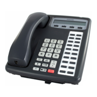
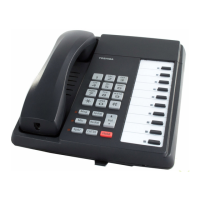
Figure 4-1 MDF Wiring for Digital Telephones (DKTs) and DDSS Console to PDKU
1
2
3
4
5
6
7
8
9
10
11
12
13
14
15
16
17
18
19
20
21
22
23
24
25
26
27
28
29
30
31
32
33
34
35
36
37
38
39
40
41
42
43
44
45
46
47
48
49
50
1
2
3
4
5
6
7
8
9
10
11
12
13
14
15
16
17
18
19
20
21
22
23
24
25
26
27
28
29
30
31
32
33
34
35
36
37
38
39
40
41
42
43
44
45
46
47
48
49
50
W-BL
BL-W
W-O
O-W
W-GN
GN-W
W-BR
BR-W
W-S
S-W
R-BL
BL-R
R-O
O-R
R-GN
GN-R
R-BR
BR-R
R-S
S-R
BK-BL
BL-BK
BK-O
O-BK
BK-GN
GN-BK
BK-BR
BR-BK
BK-S
S-BK
Y-BL
BL-Y
Y-O
O-Y
Y-GN
GN-Y
Y-BR
BR-Y
Y-S
S-Y
V-BL
BL-V
V-O
O-V
V-GN
GN-V
V-BR
BR-V
V-S
S-V
26
1
27
2
28
3
29
4
30
5
31
6
32
7
33
8
34
9
35
10
36
11
37
12
38
13
39
14
40
15
41
16
42
17
43
18
44
19
45
20
46
21
47
22
48
23
49
24
50
25
KRONE
237A
To PDKU
W/Female Connector
25-Pair Cable W/Male Amp Connector
Circuit 2 to DKT 2
Circuit 3 to DKT 3
Circuit 4 to DKT 4
Circuit 6 to DKT 6
Circuit 7 to DKT 7
Circuit 5 to DKT 5
or DDCB
(-) A1 (Voice/Data)
(GND) B1 (Voice/Data)
(-) PA1 (Add, Power)
(GND) PB1 (Add. Power)
A2
B2
PA2
PB2
A3
B3
PA3
PB3
A4
B4
PA4
PB4
A5
B5
PA5
PB5
A6
B6
PA6
PB6
A7
B7
PA7
PB7
(-) A8 (Voice/Data)
(GND) B8 (Voice/Data)
(-) PA (Add Power)
(GND) PB (Add Power)
Not Used
654321
34
25
PB AB PA
Jacketed Twisted Pairs
CW1308 0.5mm
Station Cabling
654321
34
25
PB AB PA
Digital Telephone
DDSS Console
(Circuit 8 Only)
or...
Digital
Telephone (DKT 8)
(See Note 1)
Modular
Cord
Modular
Cord
BS6312
BS6312

 Loading...

