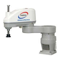
STE 80747
– 24 –
DUST-PROOF & DRIP-PROOF TYPE SPECIFICATIONS MANUAL
3.6 Cable Connection
The connector layout on the controller side and the connection method are the same
as those for the standard robots. Refer to the TH650A Installation and Transportation
Manual provided separately.
For the dust-proof and drip-proof type robot, the connector on the robot side differs
from that of the standard robots.
This paragraph describes the cable connection on the robot side.
3.6.1 Cables between Robot and Controller
!
CAUTION
• The robot controller and connector on the robot controller side are not dust-
proof and drip-proof construction.
3.6.2 Connecting and Disconnecting Connectors
!
CAUTION
• Before connecting or disconnecting the cable to or from the controller, turn
off the main power (POWER) switch.
• When disconnecting a cable, be sure to hold the connector body by hand to
pull it out. If you pull out the cable, the cable may be broken.
Motor encoder cable
connector
Square connector
(CN3)
Motor drive cable
connector
Round connector
(CN2)
Connector on robot side (CN20)
Robot control signal
cable connector
Square connector
(CN4)
Connector on controller side
Square connector (dust-
proof and drip-proof
specifications)
Gray (thin)
Black (thin)
Gray (thick)

 Loading...