2. System component
29
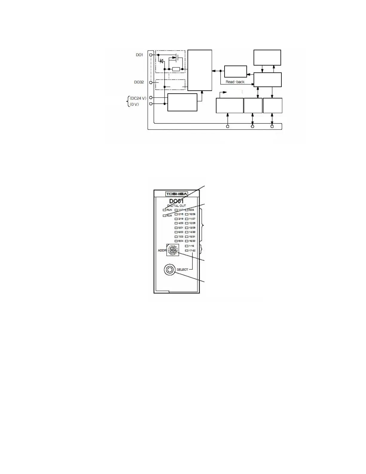
Fig. 2.22 SDO01 module internal circuit
Fig. 2.23 SDO01 module front part
RS-485
transceiver
Module connector
State
display/switch
RS-485
transceiver
Internal power
supply
System power supply
(DC24V)
Redundancy I/O bus
Bus A Bus B
External power supply
Photo-
coupler
insulating
circuit
Output
latch circuit
Internal
CPU circuit
External power
supply constant
voltage circuit
Constant voltage
power circuit
RUN indicator: Illuminates when normal
Alarm indicator: Blinks upon an error
Input data indicator:
Display changes by 16 points.
Data group indicator
Module address setting switch:
Set the module number 1 to E (1 to
Display changeover switch:
Switches between display data by 16 points.
 Loading...


