3.
System Configuration Unit and Module
43
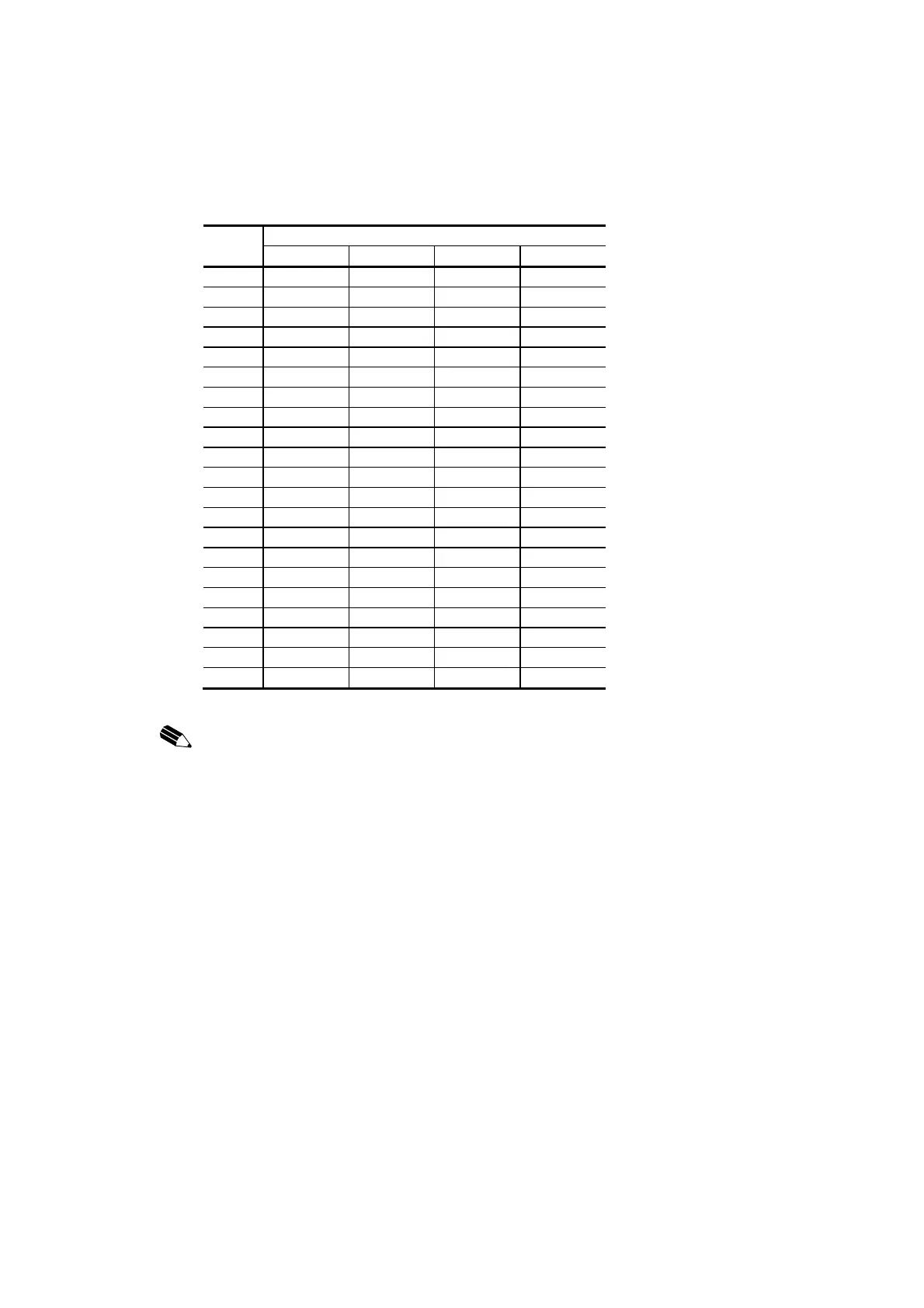
UTBA2 terminal block (TB1, TB2) signal table
TB1 PI/O module
TB2 SAI02 SAI03 SRT01 SAO02
FG (0) FG FG FG FG
1 AI1 (+) AI1 (+) RTD1 (A) AO1 (+)
2 AI1 (-) AI1 (-) RTD1 (B) AO1 (-)
3 DP1 RTD1 (b)
4 Shield 1 Shield 1 Shield 1 Shield 1
5 AI2 (+) AI2 (+) RTD2 (A) AO2 (+)
6 AI2 (-) AI2 (-) RTD2 (B) AO2 (-)
7 DP2 RTD2 (b)
8 Shield 2 Shield 2 Shield 2 Shield 2
9 AI3 (+) AI3 (+) RTD3 (A) AO3 (+)
10 AI3 (-) AI3 (-) RTD3 (B) AO3 (-)
11 DP3 RTD3 (b)
12 Shield 3 Shield 3 Shield 3 Shield 3
13 AI4 (+) AI4 (+) RTD4 (A) AO4 (+)
14 AI4 (-) AI4 (-) RTD4 (B) AO4 (-)
15 DP4 RTD4 (b)
16 Shield 4 Shield 4 Shield 4 Shield 4
17
18
19
20
NOTICE:
Before mounting a PI/O module, check to make sure that the connected signal matches
the mounted PI/O module rating.
If a PI/O module is mounted and an erroneous signal is connected, the PI/O module or external
sensor may got damage.
Each terminal block shield (4 terminals) is connected internally to each FG terminal.
The shield and PI/O are grounded by grounding the FG terminals. Always ground them.
Otherwise parts will be damaged or system will be malfunction.
Do not connect an external signal line or power supply line to an open terminal.
Doing so may cause parts to be damaged or malfunction.
 Loading...


