Do you have a question about the Toshiba tosvert VF-SXN and is the answer not in the manual?
| Brand | Toshiba |
|---|---|
| Model | tosvert VF-SXN |
| Category | Industrial Electrical |
| Language | English |
Guidelines to prevent electric shock, including checking power status and grounding.
Information regarding the inverter's retry function and when it is activated.
Safety guidelines to prevent fire hazards when operating the inverter.
Indicates where to find additional cautionary information in other chapters.
Illustrates typical wiring configurations for connecting the inverter to power and loads.
Explains the function of each terminal on the inverter's connection block.
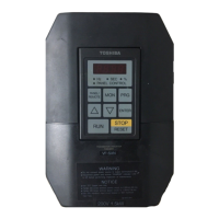
Details the components and functions of the inverter's control panel.
Step-by-step guide for starting, stopping, and basic operation of the inverter.
Details various inverter display modes: Drive, Monitoring, Programming, and Jogging.
Guides on selecting command modes for operation and parameter settings.
Configuration for parameter setting disable selection.
Procedure for setting standard parameter groups for operation.
Instructions on how to select and use different stopping methods via the panel.
Steps to reset the inverter after a trip or error condition.
Configures voltage and frequency settings, including maximum frequency, torque boost, base frequency, and V/f patterns.
Sets acceleration/deceleration times and patterns (straight line, S-curve) for motor control.
Details operation modes: forward/reverse run, coasting stop, and emergency stop via panel or external signals.
Explains signal types, priority, and setup for external frequency control.
Defines operational frequency range by setting upper and lower limits.
Guides on operating the inverter in jogging mode, both with panel and external signals.
Configuration for operating the motor at multiple preset speeds using switches.
Setup for frequency jump function to avoid resonance points during operation.
Adjustment of the initial frequency setting for motor start-up.
Configuration of operation starting frequency and hysteresis for smooth startup.
Details DC injection braking function, including setup and operation.
Explanation of regenerative discharge brake setup and operation.
How to set and display the universal unit multiplication factor for output.
Option to change PWM carrier frequency to reduce motor noise.
Adjusting output voltage and power compensation for motor characteristics.
Configuration for slip frequency compensation to maintain constant speed under load.
Details on wiring and connecting various control signals to the inverter.
Guides for selecting input terminals for control and output terminals for status signals.
Information on connecting frequency meters and ammeters.
Wiring and setup for fault detection signals.
Setting and operation of the electronic thermal overload protection for the motor.
Configuration of the stall prevention function to protect the motor from stalling.
Choosing electronic thermal characteristics based on motor type.
Settings for retaining trip information and clearing it.
Configuration of the automatic retry function after a trip.
Functionality for managing power during momentary interruptions.
Details on different inverter models, their ratings, and key specifications.
Illustrations and measurements of the inverter's external dimensions and mounting.
Description of the optional input reactor for improving power factor and harmonic reduction.
Details of the optional radio noise reduction filter for reducing electrical noise.
Information on optional braking resistors for high-inertia loads or frequent stops.
Details on the optional cable for extending the operation panel's reach.
Lists common trip causes and provides specific remedies for each.
Covers other observed error symptoms and their corresponding solutions.
Schedule and procedures for regular maintenance and inspection to ensure reliability.
Guidelines for proper storage of the inverter unit when not in use.
Information regarding the product warranty period and coverage.
A comprehensive list of all adjustable parameters, their ranges, and functions.
Reference table for inverter trip codes and their meanings.
Shows how input terminals and command modes are interrelated.
Diagrams illustrating the function of input and output terminals.
Chart showing character codes used for display and input.