5. PART CONFIGURATION AND THEIR SYMBOLS
5-1. Precautions For Part Replacement
* In the schematic diagram, parts marked (ex. F801) are critical part to meet the safety regulations, so always
use the parts bearing specified part codes (SN) when replacing them.
* Using the parts other than those specified shall violate the regulations, and may cause troubles such as operation
failures, fire, etc.
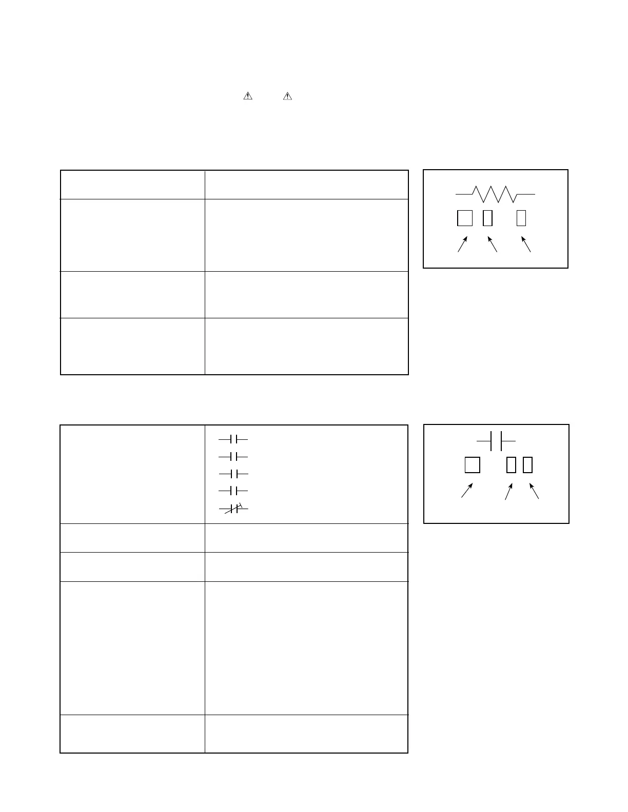
5-2. Solid Resistor Indication
Unit None • • • Ω
k • • • kΩ
M • • • MΩ
Tolerance None • • • ± 5 %
B • • • ± 0.1 %
C • • • ± 0.25 %
D • • • ± 0.5 %
F • • • ± 1 %
G • • • ± 2 %
K • • • ± 10 %
M • • • ± 20 %
Rated Wattage (1) Chip Parts
None • • • 1/16 W
(2) Other Parts
None • • • 1/6 W
Other than above, described in the Circuit Diagram
Type None • • • Carbon film
S • • • Solid
R • • • Oxide metal film
W • • • Metal film
W • • • Cement
RF • • • Fusible
Table 5-2-1
5-3. Capacitance Indication
Symbol
• • • Electrolytic, Special electrolytic
• • • Non polarity electrolytic
• • • Ceramic, plastic
• • • Film
• • • Trimmer
Unit None • • • F
m • • • µF
p • • • pF
Rated voltage None • • • 50 V
For other than 50 V and electrolytic capacitors,
described in the Circuit Diagram.
Tolerance (1) Ceramic, plastic, and film capacitors of which
capacitance are more than 10 pF.
None • • • ± 5 % or more
B • • • ± 0.1 %
C • • • ± 0.25 %
D • • • ± 0.5 %
F • • • ± 1 %
G • • • ± 2 %
(2) Ceramic, plastic, and film capacitors of which
capacitance are 10 pF or less.
None • • • more than ± 5 pF
B • • • ± 0.1 pF
C • • • ± 0.25 pF
(3) Electrolytic,Trimmer
Tolerance is not described.
Temperature characteristic None • • • SL
(Ceramic capacitor) For others, temperature characteristics are described.
(For capacitors of 0.01 µF and no indications are
described as F.)
Table 5-3-1
100k
Rated Wattage Type
Tolerance
Fig. 5-2-1
M
NP
+
100µ
Temparature
response
Rated
Voltage
Tolerance
Fig. 5-3-1

 Loading...