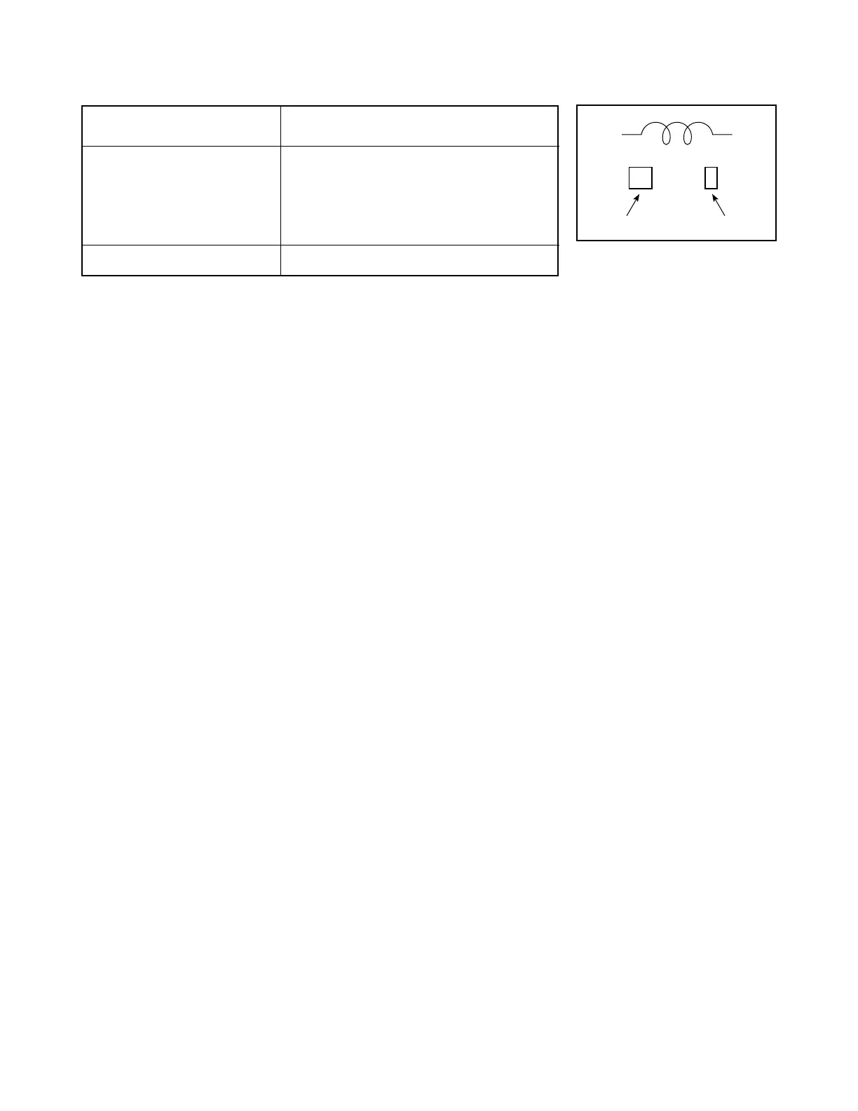
5-4. Inductor Indication
Unit None • • • H
µ • • • µH
m • • • mH
Tolerance None • • • ± 5 %
B • • • ± 0.1 %
C • • • ± 0.25 %
D • • • ± 0.5 %
F • • • ± 1 %
G • • • ± 2 %
K • • • ± 10 %
M • • • ± 20 %
Type PL • • • Peaking
For others, model name is described.
Table 5-4-1
5-5. Waveform and Voltage Measurement
* Measurement of waveform and voltage at each section in the color circuits was conducted with sufficient service color
bar signal being received and reproduced in normal conditions.
* Waveforms and voltage values for the remaining circuit were measured with a broadcasting signal normally received,
so they may vary slightly according to the programs being received. Use them as a measure for servicing.
* All voltage values except the waveforms are expressed in DC and measured by a digital voltmeter.
Fig. 5-4-1

 Loading...