2-7
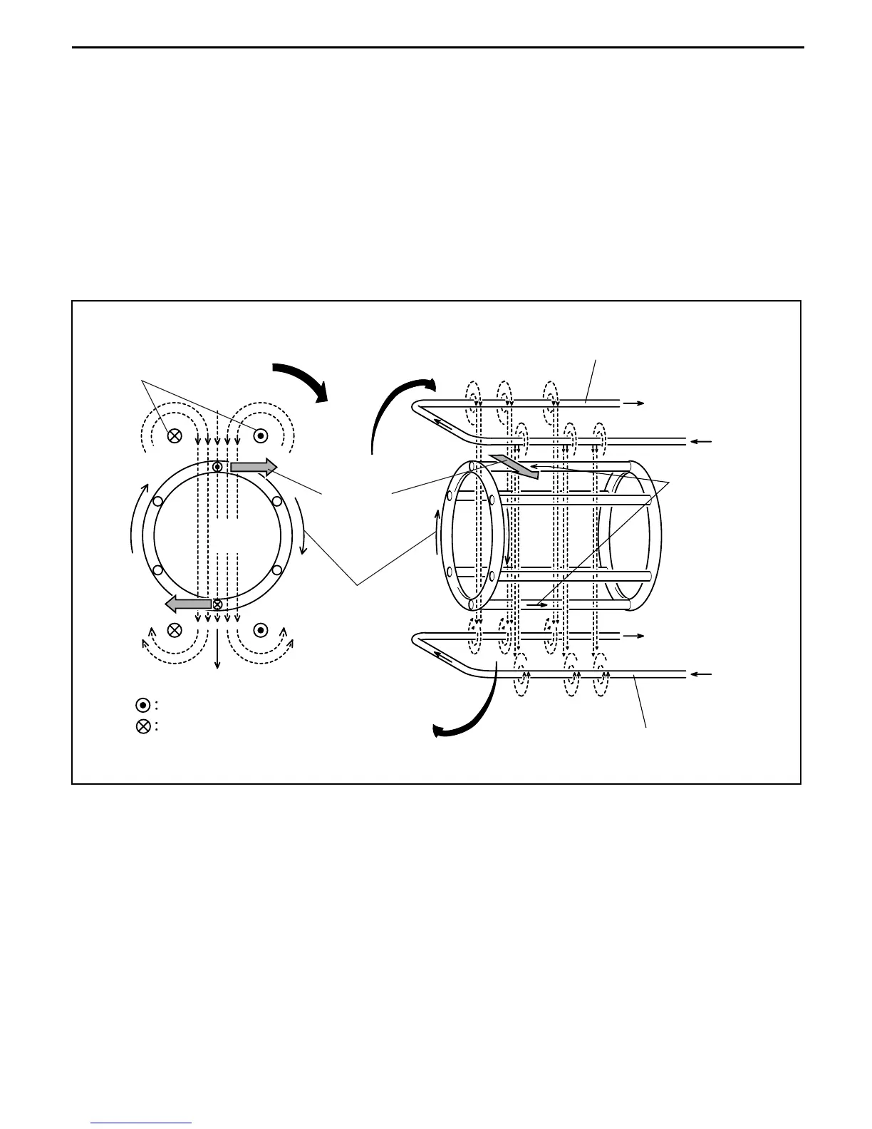
Operation principle
1. When a current flows in a fixed direction in the field winding as shown below, magnetic field is
generated around the field winding as illustrated according to the right-hand screw rule and magnetic
poles (N and S poles) are generated.
2. Clockwise rotation of the magnetic poles here is the same as counterclockwise rotation of rotor bars.
3. A current is induced in each rotor bar in the illustrated direction according to Fleming's right-hand rule.
4. The induced current in each rotor bar generates a clockwise force according to Fleming's left-hand
rule.
5. A rotating torque is generated by the electromagnetic force as explained above. The rotating speed of
the rotor is slightly less than that of the filed poles.
6. Actually, the outer field winding does not move. The sine wave of each phase of the three-phase
alternate current generates a rotational magnetic field to generate a rotating torque of the rotor.
Rotational
direction
magnetic
of pole
Rotational
direction
magnetic
of pole
Rotational direction
magnetic of pole
N pole
Field winding
Direction
of force
Current flow from the rear to the front
S pole
Current flow from the front to the rear
Direction
of force
Rotational
direction of
cage rotor
Magnetic field
Magnetic field
Field winding
Rotor (Field winding)
Direction of
current induced
in the bar
Direction
of current
Direction
of current
Magnetic
field
 Loading...