Do you have a question about the Toyotomi Kuro MTN A235DV and is the answer not in the manual?
| Brand | Toyotomi |
|---|---|
| Model | Kuro MTN A235DV |
| Category | Air Conditioner |
| Language | English |
Instructions to prevent injury to users and property damage during operation and installation.
Critical warnings for safe operation, including electrical hazards and installation risks.
Overview of functions controlled by the indoor unit, including sensors and fan control.
Key operational features of the outdoor unit, such as fan system and anti-rust cabinet.
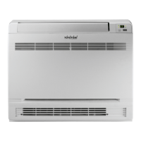
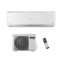
Physical dimensions (W, H, L) for the indoor units MTN A228DV and MTN A235DV.
Physical dimensions and connection port details for the outdoor units MTG A228DV and MTG A235DV.
Detailed comparison of specifications for MTN/MTG A228DV and MTN/MTG A235DV models.
Schematic diagram illustrating the internal wiring connections for the indoor unit.
Schematic diagram illustrating the internal wiring connections for the outdoor unit.
Required torque values for tightening flare nuts during installation.
Guidelines for selecting appropriate power cord gauge based on unit model.
Limits for refrigerant pipe length and vertical elevation between units.
Steps to remove air and moisture from the refrigerant piping system.
Procedure for safely recovering refrigerant during unit re-installation.
Procedure for purging air after refrigerant recovery during re-installation.
Method for balancing refrigerant charge using 2-way and 3-way valves.
Steps for creating a vacuum in the refrigerant system to remove moisture.
Procedure for charging the system with the correct amount of refrigerant.
Graphs showing cooling and heating performance vs. ambient temperature and piping length.
Graphs showing cooling and heating performance vs. ambient temperature and piping length.
Definitions of common abbreviations used for sensors and parameters (T1-T4).
Explanation of LED icons on the indoor unit display and remote control functions.
Overview of built-in protection mechanisms for the compressor and overall unit operation.
Specific operational rules and protections during the cooling mode, including anti-freezing.
Functional aspects and controls specific to the drying mode of operation.
Details on indoor fan control, auto fan, and compressor operation during heating.
Criteria that trigger the automatic defrosting cycle and conditions for ending it.
Diagram illustrating the sequence of compressor, valve, and fan actions during defrosting.
Procedure for activating and deactivating the rating capacity test mode for performance verification.
How the Turbo mode enhances heating performance, including fan speed and compressor frequency.
Logic for automatic mode selection based on temperature difference (ΔT).
Methods for manually initiating forced auto or forced cooling operations.
Operation of the 4-way valve in different modes like cooling, heating, and defrosting.
Fan speed control for the outdoor unit in various operating modes.
Options and tolerance for setting on, off, and on/off timer functions.
How sleep mode adjusts temperature and fan speed for energy saving and comfort.
System behavior to restore previous settings after a power interruption.
Operation of the optional Plasma dust collector feature activated via the TURBO button.
Function and operating temperature range of the outdoor unit's anti-freezing heating cable.
Critical safety warnings regarding high voltage capacitors before performing checks.
Table mapping failure phenomena to indicator lamp states for indoor unit errors.
Diagnostic flowcharts for common communication and zero-crossing signal errors.
Procedures for measuring resistance of compressor and step motor windings.
Resistance-temperature data and graph for key temperature sensors.