Switching Configuration Examples
User Guide
33
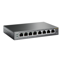
Figure 5-5 Network Topology for LAG
Switch A Switch B
Hosts
Port 1
Port 1
Port 3
Port 3
Servers
Port 2 Port 2
Demonstrated with TL-SG105E, the following section provides configuration steps. The
configuration steps are similar for both switches, here we take Switch A for example.
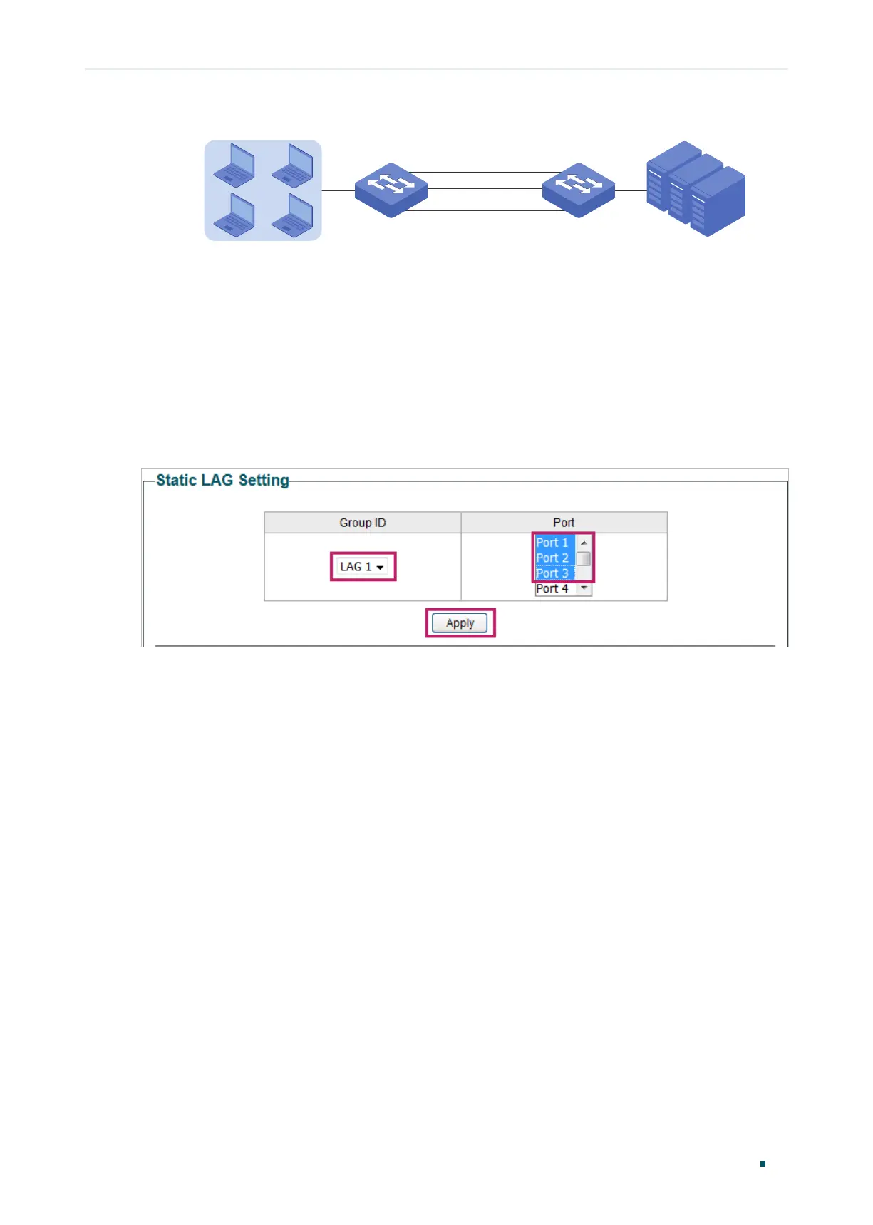
5.2.2 Configuration Steps
Choose the menu Switching > LAG to load the following page. Add Port 1, Port 2 and Port
3 to LAG 1. Click Apply.
Figure 5-6 Configuring LAG
 Loading...