WARNING: Risk of Electric Shocks
• Disconnect power at the fuse or circuit breaker before installing.
• Verify that the power supply voltage is correct. Connect xture to a 110-240 VAC
50/60 Hz power source.
• Always follow code standards when installing wired connections.
• Install only on a UL-listed junction box or on a wall with a Neutral wire and a Line wire.
• An all-pole mains switch shall be incorporated in the electrical installation of the
building. And the contact separation of the switch shall not be less than 3 mm.
• You can always nd detailed wiring and mounting instructions in the Tapo app.
If you are unfamiliar with basic electrical wiring, please consult a licensed electrician.
OR
Tapo
Before You Start
NOTICE
• Do not install near combustible or ammable surfaces.
• Do not connect this light xture to a dimmer switch or timer.
Tapo Smart Floodlight Camera
Quick Start Guide
©2023 TP-Link 7106510763 REV1.3.0
*Images may dier from actual products.
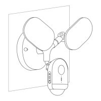
You can mount your Tapo oodlight camera vertically on a wall or overhang under an eave. Make sure the area has a strong Wi-Fi signal.
01 / Mounting Options
Wall Mount
OR
Eave Mount
Take care to avoid electric shocks.
For Wall Mount
Ensure the UP arrow on the
bracket points up.
*To install horizontally, adjust the bracket to ensure
the air bubble in the level is centered.
Point the UP arrow on the bracket
towards your house.
For Eave Mount
*Wire colors vary by region. If you are unfamiliar with basic electrical wiring, please consult a licensed electrician.
02 / Connect Wires and Install Floodlight Camera
2
Remove the existing oodlight camera and
disconnect wires from the junction box.
1
Turn o the circuit breaker. Make sure the power
is o by turning your light on and o a few times.
The oodlight camera can be mounted on a junction box on a wall or under an eave.
Required Accessories:
Option 1: Install on an existing junction box
OFF
3
Choose a pair of plate screws based on your
junction box. Install the mounting plate to
the junction box.
4
Cover the Ground wire (usually green/green
and yellow) with the provided wire nut. Route
the Neutral wire (usually white/blue)
and the Line wire (usually black/brown/red)
through the bracket.
Take care to avoid electric shocks.
6
Hide the wires in the junction box.
Attach the bracket to the mounting plate
on the junction box with the bracket screw.
7
Insert the camera screws into the screw holes.
Align the mounting posts on the bracket with
the holes on the oodlight camera.
Tighten the camera screws in the screw holes
to secure the oodlight camera to the bracket.
Insert the screw caps into the screw holes.
8
Adjust the camera and light position to the
desired angles.
9
Turn on the circuit breaker.
5
Connect the Neutral wire and Line wire to
the bracket. Secure the wires with a slotted
screwdriver.
L
(Line)
N
(Neutral)
L
(Line)
N
(Neutral)
5
Connect the Neutral wire (usually white/blue)
and the Line wire (usually black/brown/red) to
the bracket. Secure the wires with a slotted
screwdriver.
2
Route the wires through the mounting template
and place the template. Drill two holes where
indicated.
3
Insert two wall anchors into the holes. Route
the wires through the mounting bracket. Use
the screws to ax the bracket over the
anchors.
Option 2: Install with existing electrical wires
Install where the Neutral wire and Line wire are available.
OFF
1
Turn o the circuit breaker. Make sure the power
is o by turning your light on and o a few times.
6
Hide the wires in the bracket.
Insert the camera screws into the screw holes.
Align the mounting posts on the bracket with
the holes on the oodlight camera.
Tighten the camera screws in the screw holes
to secure the oodlight camera to the bracket.
Insert the screw caps into the screw holes.
7
Adjust the camera and light position to the
desired angles.
8
Turn on the circuit breaker.
4
Cover the Ground wire (usually green/green
and yellow) with the provided wire nut.
Take care to avoid electric shocks.
Note: To identify wire colors, you can refer to
https://www.tp-link.com/support/faq/3474/
Note: To identify wire colors, you can refer to
https://www.tp-link.com/support/faq/3474/
Note: If the wires are too short or sti to connect:
1) Align the Neutral wire (Recommended wire stripping
length: 10 mm) with the white extension wire ends.
2) Place one wire nut connector over the wires. Twist
the wire nut clockwise to tighten the wires.
3) Repeat the above steps to extend the Line wire
using the black extension wire and another wire nut.
Bracket
Screw
Camera Screws ×2 +
Screw Caps ×2
(Optional) Wire Nuts ×3 +
Extension Wires ×2
Mounting Plate + Plate Screws ×2
(Choose screws based on your junction box)
Type A Type B Type C
Mounting
Bracket
Anchors ×2 +
Mounting Screws ×2
Camera Screws ×2 +
Screw Caps ×2
(Optional) Wire Nuts ×3 +
Extension Wires ×2
Mounting
Template
Mounting
Bracket
Required Accessories: