➌ When connecting the tubing, push in a
clockwise twisting motion. This helps you
to avoid loosening the barb fitting.
➍ Make sure there are no kinks in the tubing.
Input Configuration
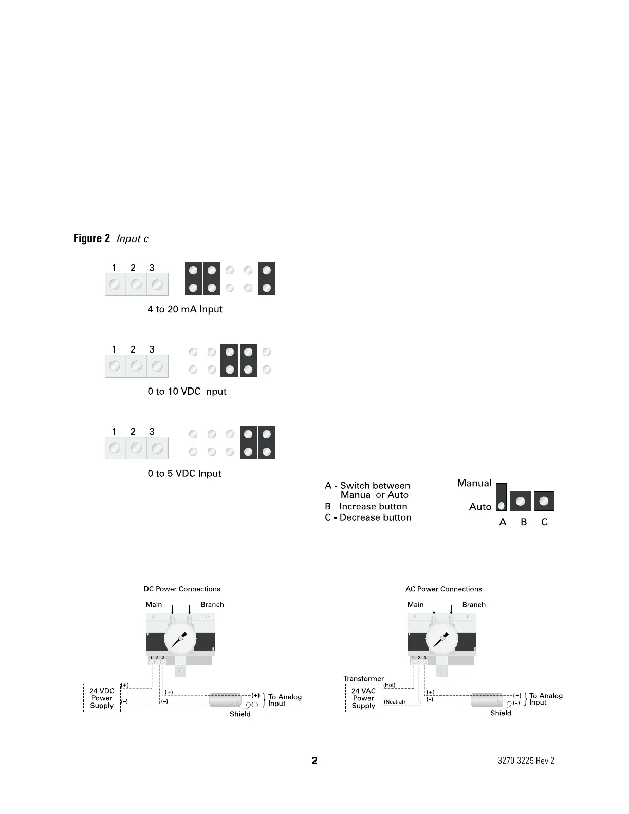
Select the input configuration using figure 2. The
transducer is configured for 4 to 20 mA input. To
change the input configuration, configure the
shorting plugs as shown in figure 2.
Power Connections
Universal 24
VAC/24 VDC supply voltage and
field selectable inputs ensure one unit
compatibility to most of the systems.
➊ Follow the wiring diagram in figure 3.
Check wiring before applying power.
➋ Select input configuration before
applying power.
➌ Do not reverse polarity.
➍ When using more than one transducer with the
same power source, polarity must be observed.
Note: Analog output wire must be 18 or 22 gauge
shielded twisted pair (equivalent to Trane
BASD
wire # 400 2028). Cut back and tape the shield at
the transducer.
The gauge on the transducer is for indication
only. The unit’s calibration is far more accurate
than the accuracy of the gauge.
Manual Override
The Electropneumatic Transducer has the
capability to operate in manual or auto
configuration. The default factory setting is to
the auto position. The output pressure is based
on the input signal supplied to the transducer
when configured to auto. In the manual
position, the transducer increases or decreases
output pressure based on the settings of the
override buttons as shown in figure 4.
2
3270 3225 Rev 2
Figure 2 Input configuration for the transducer
Figure 3 Power connections for the Electropneumatic Transducer
Figure 4 Configuration of transducer
 Loading...