4. Loosen hose clamp at top of canister. Slide steam hose off top of
canister (see FIGURE 19).
5. Slide canister up and out of drain assembly (see FIGURE 19).
Discard old canister.
6. Remove O-ring from drain assembly using small screwdriver.
Discard old O-ring.
7. With your finger, swirl the fluid/precipitate mixture in the bottom of
the drain valve reservoir (see FIGURE 19).
8. Using a sponge or paper towels, soak up the water in the reservoir.
If necessary, use a wet/dry vacuum to remove residue.
9. Clean the inside of the drain port (where coil projects out) by gently
swabbing with a bent cotton swab or other soft implement.
10. Rinse the drain valve reservoir with clean water and vacuum as
necessary.
11. Insert new O-ring (O-ring is provided with Model 8043RP and
Model 8043LCRP canisters) into slot in drain assembly. Dampen
O-ring with water before inserting canister. Do not use oil, grease,
or any lubricant besides water.
12. Make sure strainer is inserted into bottom of new canister.
13. Insert new canister into drain assembly (see FIGURE 19).
14. Slip steam hose over top of canister and tighten hose lamp (see
FIGURE 19).
15. Reconnect the electrode wires and water level probe wire to
the posts on top of the canister (see FIGURE 17A and FIGURE
17B). Electrode wires are interchangeable and can be placed on
either of the two electrode posts on top of the canister. Ensure
connectors are fully seated.
ELECTRODE WIRE REPLACEMENT
1. Remove front panel (see FIGURE 16).
2. Remove side panel (see FIGURE 16).
3. Remove the electrode wires (see FIGURE 17A and FIGURE 17B).
a. For units with one circuit board: Use needle nose pliers to pull
the spade connectors off spade terminals J8 and J10 on the
circuit board.
b. For units with two circuit boards: Use needle nose pliers to pull
the spade connectors off the spade terminals on the power relay.
4. Ensure the two replacement electrode wires (Part #5614RP) have
“O” shape connectors (see FIGURE 18B). Do not use replacement
wires with “D” shape connectors (see FIGURE 18A).
5. Attach the new electrode wires (see FIGURE 17A and
FIGURE 17B).
a. For units with one circuit board: Use a pair of needle nose pliers
to attach the spade connectors to the spade terminals J8 and
J10 on the circuit board. Electrode wires are interchangeable and
can be placed on either of the two terminals.
b. For units with two circuit boards: Use a pair of needle nose pliers
to attach the connectors to the spade terminals on the power
relay. One wire, either one but not both, must go through
current-sensing toroid (see FIGURE 17A). Electrode wires
are interchangeable and can be placed on either of the two
terminals.
FILL VALVE SERVICE
1. Disconnect water supply line from fill valve inlet (see FIGURE 19).
2. Remove in-line strainer from the fill valve inlet port using a #8 or
#10 sheet metal or wood screw with a minimum length of 0.5”.
3. Clean or replace in-line strainer (Part #4529RP).
4. Reconnect water supply line to fill valve inlet (see FIGURE 19).
RESTORE UNIT TO SERVICE
1. Replace side panel if removed (see FIGURE 16).
2. Replace front panel (see FIGURE 16).
3. Inspect drain hose to make sure it is not blocked and has constant
downward slope. Clean or replace if necessary.
4. Inspect and clean condensate pump (if used).
5. Inspect steam hose to make sure it has no low spots and has
constant upward slope from humidifier to dispersion tube in duct. If
dispersion tube is mounted below humidifier, inspect drip tee and
drain trap.
6. Restore main electrical power to humidifier at circuit breaker.
7. Turn humidifier on and verify green On/Off light is illuminated (see
FIGURE 16).
8. Check system operation and inspect all plumbing connections and
piping for signs of cracks or leaks.
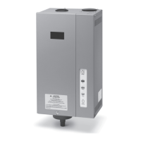
STEAM
OUTLET
SUPPLY
WATER
DRAIN CUP
DRAIN VALVE
ELECTRODES
WATER LEVEL PROBE
FILL
STEAM HOSE
DISPERSION
TUBE IN DUCT
TUBELETS
CANISTER
90-1522
FIGURE 19 – Fill & Drain System and Canister
MAINTENANCE (CONTINUED)
22
 Loading...