NOTE: The wiring diagrams in this guide are included as a reference. The manufacturer
has a policy of continuous product and product data improvement and reserves the right
to change design and specifications without notice. Always check the unit nameplate and
wiring diagram for the actual unit requirements.
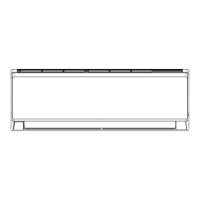
Indoor Cooling and Heat Pump Unit 18K
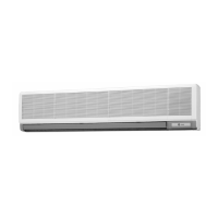
Indoor Cooling and Heat Pump Unit 24K
MAIN BOARD
AP2
JUMP
CAP
COM-OUT
N(N1)
STEPPING
MOTOR
UP-DOWN
M2
SWING-UD
BLOCK
TERMINAL
3
2
N(1)
XT1
OUTDOOR UNIT
DISP1 DISP2
AC-L
RT2
θ
TUBE TEMP.
SENSOR
RT1
θ
ROOM TEMP.
SENSOR
COM-MANUAL
AP5
WIRED
CONTROLLER
WH(BU)
BK
RD(BN)
GN(YEGN)
AP4
M3
SWING-LR
STEPPING
MOTOR
LEFT-RIGHT
AP3
DISPLAY
RECEIVER AND
DISPLAY BOARD
AP1
G
EVAPORATOR
YEGN
BN
BK
BU
OPTIONAL
OPTIONAL
GATE
CONTROL
DOOR-C
(DRY-C)
PG
PGF
M1
FAN MOTOR
OPTIONAL
OPTIONAL
WIFI
MODULE
WIFI
T-SENSOR
MAIN BOARD
AP2
JUMP
CAP
COM-OUT
N(N1)
AP4
STEPPING
MOTOR
M3
UP-DOWN
SWING-LR
M2
STEPPING
MOTOR
LEFT-RIGHT
SWING-UD
BLOCK
TERMINAL
3
2
N(1)
XT1
OUTDOOR UNIT
DISP1DISP2
AC-L
T-SENSOR
RT2
θ
TUBE TEMP.
SENSOR
RT1
θ
ROOM TEMP.
SENSOR
COM-MANUAL
AP3
WIRED
CONTROLLER
WH(BU)
BK
RD(BN)
GN(YEGN)
AP5
RECEIVER AND
DISPLAY BOARD
AP1
OPTIONAL
OPTIONAL
G
EVAPORATOR
YEGN
DC-MOTOR
M1
FAN MOTOR
BN
BK
BU
WIFI
MODULE
OPTIONAL
OPTIONAL
GATE
CONTROL
(DOOR-C)
DRY-C
WIFI
32 88-M4MHW17-1B-EN
Installer's Guide

 Loading...


