TK 53050-3-OP-EN
19
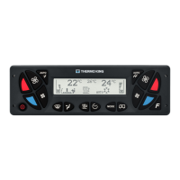
LCD Graphic Display
Figure 1. LCD Graphic’s display
1 12 7
2 3 4 5 6 11 10 9 8
BED776
1.
Driver's area temperature set point
(a)
7.
Passenger's area temperature set
point
(b)
2.
Driver's area – air flow indicator
(Front Box blower speed)
8.
Passenger's area – air flow indicator
(HVAC unit blower speed)
3.
Air flow direction (air distribution
damper position) indicator
9. SMOG icon
4. Automatic mode of Front Box icon 10.
HVAC unit operating mode icon
5. Preheater icon 11. Automatic mode of HVAC unit icon
6. Preheater timer icon 12.
Ambient temperature
(c)
(a)
Depends on system configuration, driver panel or CANAIRE system setting.
(b)
Depends on system configuration, driver panel or CANAIRE system setting.
(c)
Depends on system configuration, driver panel or CANAIRE system setting.
Alarms Icons
Warning:
"YELLOW Alarm" ► long beep ► HVAC unit is operating, probably with some
restriction ► arrange repair as soon as possible.
Alarm:
"RED Alarm" ► long beep and then short beeps repeatedly ► HVAC unit is
operating in VENTILATION Mode only ► arrange repair IMMEDIATELY.
CCAANNAAIIRREE CCoonnttrroolllleerr

 Loading...


