Do you have a question about the TRC Surge Guard 40350 RVC and is the answer not in the manual?
Check ATS grounding. Ensure green wire is attached to terminal block and grounded to RV.
Verify incoming generator voltage is within 102-132V.
Check incoming frequency is within 55-70 Hz.
Check input power connections for faults and generator breaker status.
Ensure L1 and L2 are not mis-wired into the neutral terminal.
Indicates a blown fuse for surge protectors on the control board.
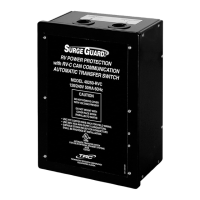
The Surge Guard Model 40350 RVC is an Automatic Transfer Switch (ATS) designed for RV power protection. Its primary function is to safeguard your recreational vehicle from low-quality power sources by automatically switching between available power inputs, such as shore power and generator power. This device incorporates several protective features, including defense against high voltage, low voltage, and incorrectly connected chassis ground.
When any of these fault conditions are detected, the ATS will open both contactors to protect the RV's electrical system. Once the fault condition is resolved, the ATS initiates a delay of approximately 2.5 minutes before attempting to re-engage the appropriate contactor. This delay ensures that the power source has stabilized before reconnecting the RV.
The ATS is equipped with an optional 40299 Remote LCD Display that provides valuable feedback to the user. If the ATS fails to close a contactor or transfer power as expected, the display will show an error message. These messages, such as "Loss of Ground," "High Volt," or "Reverse Polarity," indicate specific fault conditions that must be corrected for the transfer switch to operate correctly. If the display reads "Delay Active" instead of an error message, it signifies that a fault condition has cleared, and the switch is undergoing its 2.5-minute delay before attempting to reconnect.
For troubleshooting, if no display is available, users should check the input voltage level to ensure it falls within the proper operating limits. It's also crucial to verify that the ATS is correctly connected to chassis ground and that the neutral conductor is properly connected to ground at the power pedestal. A 2.5-minute wait is recommended to see if a temporary fault condition has cleared, allowing the contactor to engage.
The device's usage features include its automatic transfer capability, which seamlessly switches power sources without manual intervention. This ensures continuous power supply to the RV while protecting its electrical components from harmful power fluctuations. The ATS constantly monitors incoming frequency, ensuring it remains within the 55-70 Hz range. If the frequency falls outside these limits, the transfer switch will keep the contactor open to protect the RV.
Maintenance features primarily involve troubleshooting and verifying connections. Users are advised to regularly check the 40350 display screen for error messages, which guide them to specific issues. For instance, a "No Ground" error indicates a problem with the ATS grounding or the input power pedestal's ground. A "High/Low Voltage" error suggests that the incoming voltage is outside the acceptable 102-132V range, prompting users to adjust the generator's output or find a different shore power source. Similarly, "High/Low Frequency" errors require checking and adjusting the generator's frequency.
The "L1/L2 Open" error points to a possible faulty connection on the input power to the transfer switch, requiring users to verify all input cables and circuit breakers. The "Reverse Polarity" error signifies incorrect wiring of hot leads into the neutral terminal, necessitating a power-off inspection and correction of connections. Finally, a "Check Surge" message indicates that one of the fuses for the surge protectors on the control board has blown. While this doesn't affect normal transfer switch operation, replacing the fuse is necessary to restore surge protection capability.
Installation and maintenance also emphasize the importance of correct wiring and torque specifications. The terminal block cable installation diagram must be followed precisely, and all screws holding the input and output power cables must be fully tightened to the correct torque. Failure to do so can lead to electrical shock or fire hazards. Care must be taken to avoid cross-threading terminal screws, which could result in improper torque.
In summary, the Surge Guard Model 40350 RVC is a robust and intelligent automatic transfer switch that provides comprehensive power protection for RVs. Its automatic fault detection, error display system, and detailed troubleshooting guidelines make it a user-friendly device for maintaining the integrity of an RV's electrical system. Regular monitoring of the display and adherence to installation and maintenance instructions are key to ensuring its optimal performance and the longevity of your RV's electrical components.
| Brand | TRC |
|---|---|
| Model | Surge Guard 40350 RVC |
| Amperage | 50 Amp |
| Voltage | 120/240V |
| Surge Protection | Yes |
| Diagnostic Lights | Yes |
| Voltage Rating | 120/240V |
| Current Rating | 50A |
| Response Time | Less than 1 nanosecond |
| Type | Surge Protector |
| Operating Temperature | -40°C to 70°C |
| Wire Gauge Compatibility | 6 AWG |