18
Trevi Spa User Guidea
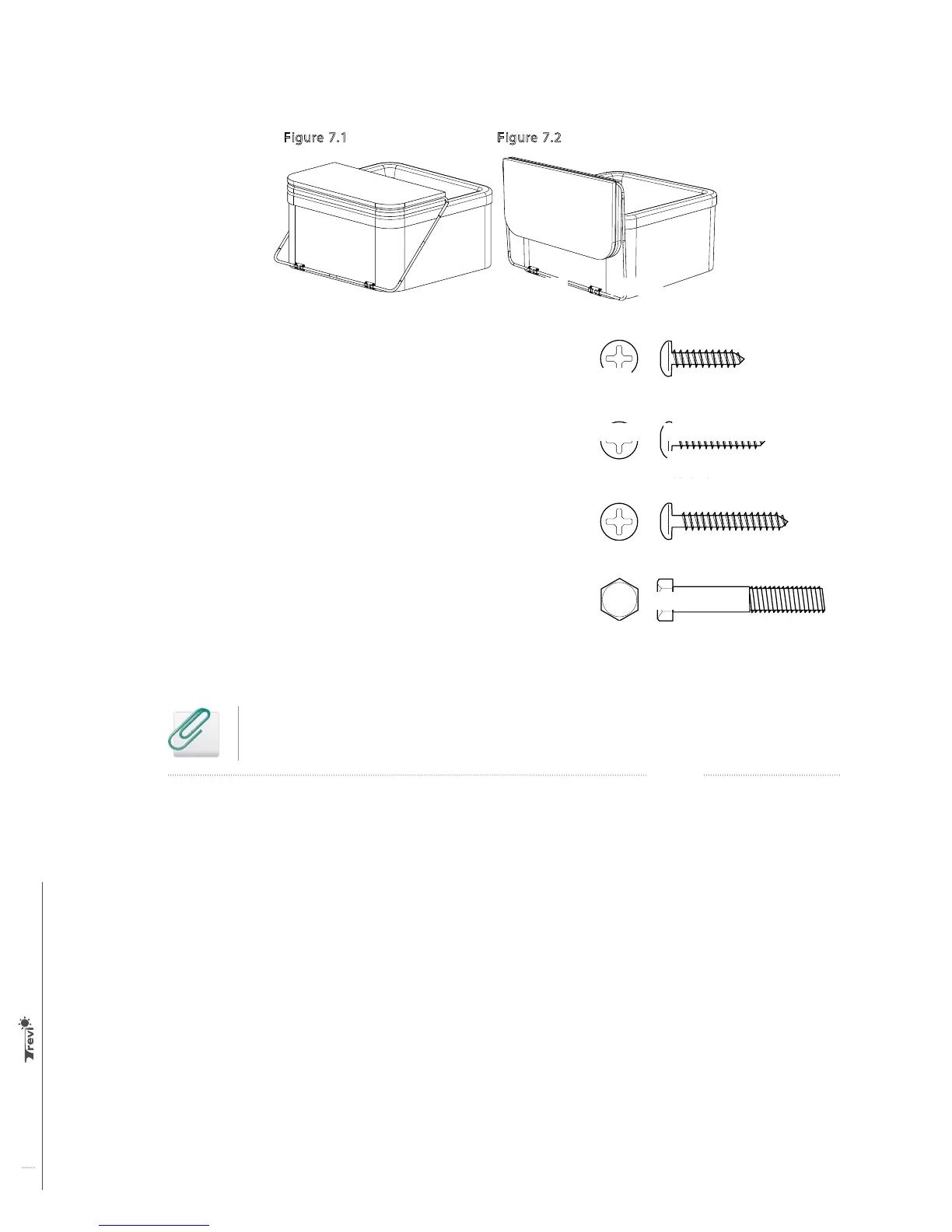
Figure 7.2
Figure 7.1
(A) “L” shaped upper corner part - 2.5 cm (1") dia. (2)
(B) Upper central tube - 2.2 cm (7/8") dia. x 110 cm (40") long (1)
(C) Upper side tube - 2.5 cm (1") dia. x 89 cm (35") long (2)
(D) Lower side tube - 28.6 cm (1 1/8") dia. x 63.5 cm (25") long (2)
(E) “L” shaped lower corner part - 28.6 cm (1 1/8") dia. (2)
(F) Lower central tube - 2.5 cm (1") dia. x 110 cm (40") long (1)
(G) Frame assembly support (2)
Belt support (2)
Belts (2)
5/16" x 1 5/8" long screw with hexagonal head and nuts (8)
¾" long self-drilling screws (18)
1" wood screws for the belt support (6)
3/16" x 1 1/4" long wood screws (6)
Flat washers (4)
Figure 7.2
Figure 5
Figure 7.1
Figure 6
13 cm
5”
18 – ¾" self-drilling screws
Figure 7.2
Figure 5
Figure 7.1
Figure 6
13 cm
5”
6 – 1" wood screws
Figure 7.2
Figure 5
Figure 7.1
Figure 6
13 cm
5”
10 - 3/16" x 1 ¼" wood screws
Figure 7.2
Figure 5
Figure 7.1
Figure 6
13 cm
5”
8 - 5/16" x 1 5/8" long screws
with hexagonal head
Installation of the hydraulic spa cover
Before you begin, please determine if you are making a surface or side installation.
NOTE: You will find the parts drawing at the end of this document.
Figure 1.1
Figure 2.1
Figure 3
Figure 2.2
Figure 1.2: Surface installation
Figure 1.3: Side installation
Cover
U-support
Spa edge
4 lag bolts
4 lag bolts
5/8" bolt
Locking
key
Stabilizer
bar
1 ¾" bolt
Pivoting arm
Nut
U-Support
Nut
Hydraulic
cylinder
Threaded
stud
Threaded
stud
Blocking
tube
Stabilizer
bar
Pivoting
bar
minimum of
4 ¾" bolts
 Loading...