Diagram 2
Sensor
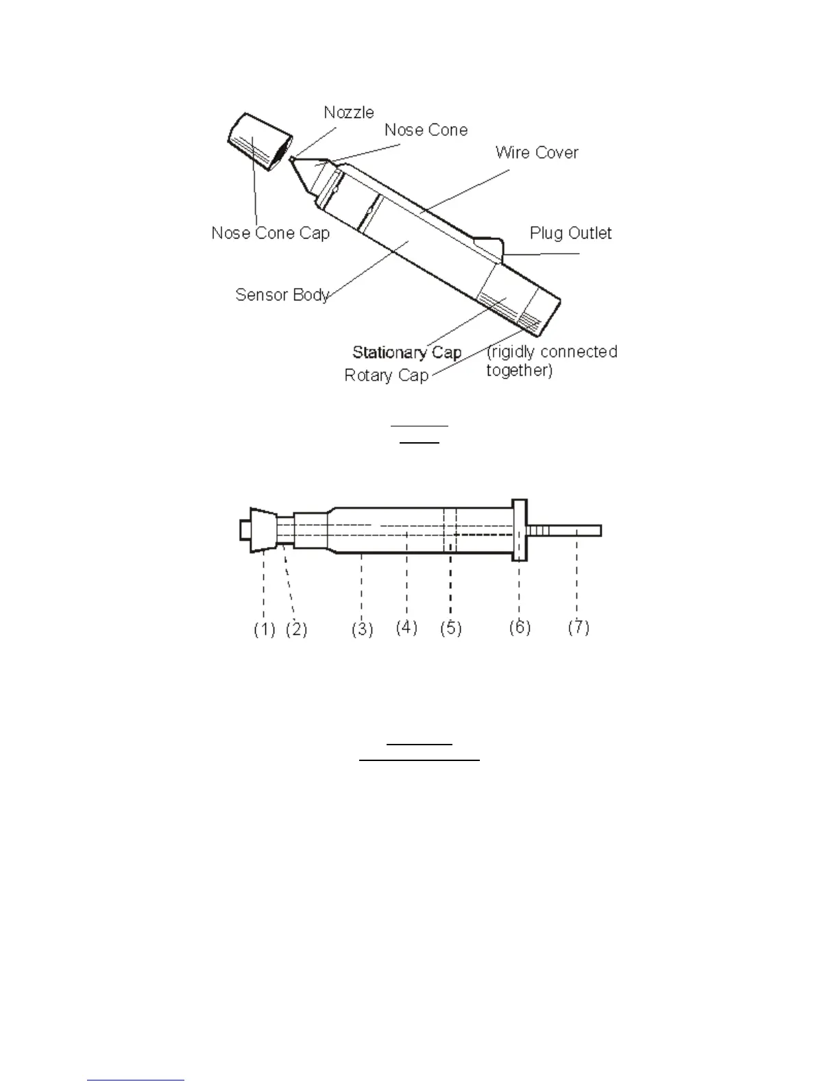
Diagram 3 shows the cross section of the polyethylene tube.
1. Tube Cap 4. Feed Screw 7.Feed Screw
2. Tube Nozzle 5. Piston Engagement
3. Tube Body 6. Bottom Plug
Diagram 3
Polyethylene Tube
When using the Sensor, be sure that:
1. The sensor nozzle is clean. Use the plastic cleaner (supplied) to clean the opening.
2. When testing, dispense THEN dispose of the drop of gel following each test. For
best result, use every other gel drop for testing.
LOADING/CHANGING THE POLYETHYLENE GEL TUBE
1. Take off the nozzle cap (Diagram 2).
2. Remove the Stationary Cap by turning the light colored barrel (Diagram 2) counter
clockwise. Please remember that the Stationary Cap and the Rotary Cap are
undetachable. (Diagram 2).