14
Extender Kit Installation (B130-101-2, B130-101A-2,
B130-101-WP-1, B130-101A-WP-1, B130-101S-2, B130-101-U)
Note:
1. For models that support EDID copy, perform the EDID copy procedure described
in this manual prior to installation.
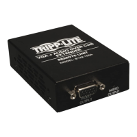
2. The diagram above shows a B130-101A-2 VGA + Audio Extender Kit installation.
Installation will be the same for other extender kit models, with the exception of
units featuring VGA + RS-232 serial or VGA only. The B130-101-U gets power
from the USB cable built-in to the local unit, and doesn’t require external power
supplies.
3. Test to make sure the entire installation works properly before pulling cables
through ceilings/walls.
4. To achieve maximum distance and performance, 24 AWG solid-wire Cat5e/6
cable must be used. The use of stranded wire Cat5e/6 cable, or cable with a
gauge (AWG) size higher than 24 AWG, will result in shorter extension distance.
All Tripp Lite N202-Series cables are made with 24 AWG solid-wire cabling.
Tripp Lite N022-01K-GY (Cat5e) and N222-01K-GY (Cat6) are 24 AWG solid-wire
bulk cables. For optimal image quality between 500 and 1,000 ft., use Zero-
Skew cable, such as Tripp Lite P524-01K. For the B130-101-U, use Zero-Skew
cable for distances between 250 and 500 ft.
5. To achieve maximum resolution, it is recommended that you use Tripp Lite
P502-Series VGA video or P504-Series VGA video and audio* cables with
RGB coax.
Installation continued
*If this is a feature of your extender kit.
Transmitter Unit
Receiver Unit
13-04-119-93-3289.indd 14 4/26/2013 2:00:23 PM
 Loading...