Model: A212636D
Airbus A330, A340, A350, McDonnell Douglas DC-10, MD-11 Towbar
12/2014 | Rev. 01 Page | 2
4.0 OPERATION (continued)
4.2 ATTACHING TO AIRCRAFT
The towbar is equipped with a clamp type attachment head. When attached properly it will allow the aircraft to be pushed or
pulled safely.
To attach the towbar to the aircraft:
1. Raise or lower the towbar so that it is level to the ground and at the same height as the nose gear attachment point
2. Open the jaws by pulling the black knob outward and opening the center jaw by pulling up on the large handle
3. Position the lower jaws under the nose gear cross shaft and clamp the middle jaw around the shaft by pushing back down
on the large handle until the black knob moves back into the locked position
4.3 ATTACHING TO TRACTOR
The towbar is equipped with a towing eye that swivels to eliminate any possible binding due to irregular terrain or camber
changes in the aircraft nose gear during pushback or towing operations.
To attach the towbar to the tractor:
1. Raise or lower the towbar so that it is level with the ground and at the same height as the tractor hitch point
2. Position the lunette eye into the hitch opening and secure the hitch pin according to the tractor manufacturer’s instructions
CAUTION!
The towbar can be safely towed on typical ramp surfaces up to 15 MPH. Exceeding this speed may result in
damage to the towbar
5.0 MAINTENANCE
5.1 GENERAL
Towbar maintenance should be done at least once every three months or sooner depending on usage.
1. Check shear bolts for wear or a partial shear and replace if necessary. Check bolts by rotating them and looking for
movement of the shear plates at the same time
2. Check shear plates for seizing from corrosion and apply a fresh coating of Permatex anti-seize lubricant or equivalent
when installing a new head assembly or shear bolts
3. Check tire pressure and inspect for wear or damage
4. Check the hydraulic fluid in the reservoir and maintain the correct level
5. Check for hydraulic leaks
6. Check all nuts, bolts and screws for tightness
7. Check the unit overall for wear or damage
8. Grease hubs through zerk provided in hub
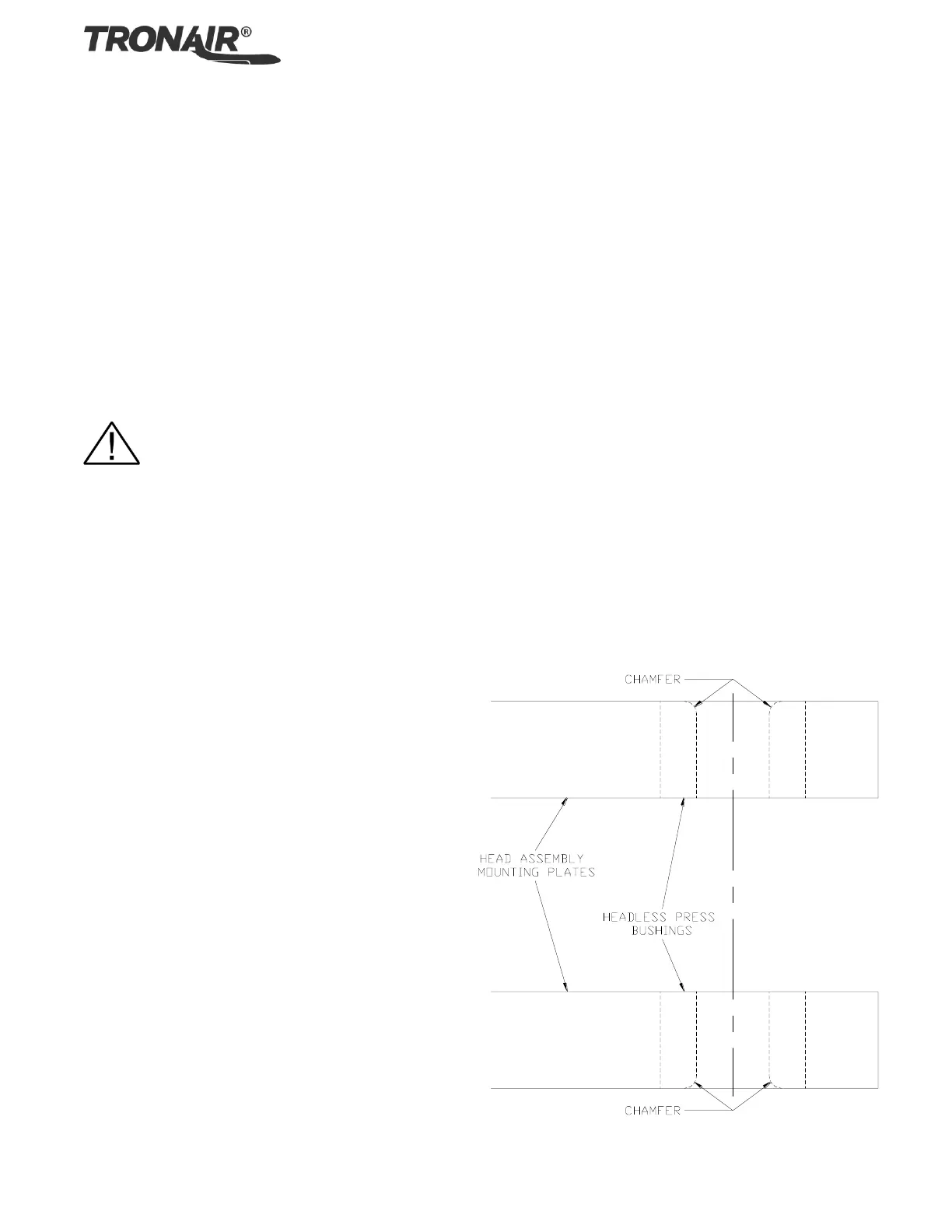
Note: When pressing in new headless press bushings
for the shear bolts, assure the chamfer is as shown.
5.0 Maintenance continued on following page.
 Loading...