8
Water pipe routing
1. Connect the cold water supply (15) via the pressure reducer
(10) to the safety/drain valve (14).
12
13
14
10
16
15
22
2. Produce connection (16) for cold water supply between
safety/ drain valve (14) and elbow (13 – lower pipe) on water
heater.
3. Route the hot water pipe (22) from the elbow with integrated
breather valve (12 – upper pipe) to the hot water consumers.
Gas connection
14 mm
14 mm
1/4"
The gas inlet connec-
tion on the Boiler is a
14 mm metric connection.
To connect, the 1/4" BSP
male gas inlet connection
provided with the appliance
must be used.
Check for gas leaks (do not check for gas leaks with a naked
flame), then check that the gas pressure is as follows:
Propane gas: 2.75 kPa
Before connecting to the water heater make sure that the gas
lines are free from dirt, chips and such!
Route the pipes in such a way that the appliance can be
removed again for servicing.
The gas system must comply with the technical and admin-
istrative regulations of the country in which the appliance is
used.
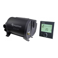
Installation of the control panels
When using control panels which are specific to the ve-
hicle or the manufacturer, the electrical connection must
be established in accordance with the Truma interface descrip-
tions (refer to Electrical connection 230 V). Any modification
made to the Truma components pertaining to this will lead to
the invalidation of the guarantee, as well as to the exclusion of
any claims for liability. The installer (manufacturer) is responsi-
ble for providing instructions for use for the user as well as for
identification printing on the control panels.
When selecting the location, bear in mind that the control pan-
els must not be subjected to direct radiant heat. Length of con-
nection cable 2.5 m. If required, a cable extension of 5 m can
be supplied (refer to last page).
66 mm
Ø 55 mm
30
29
28
28
25
32
32
26
31
31
27
25
1. The control panel for gas operation (26) and (if provided) the
control panel for electrical operation (27) should be fitted next
to one another if at all possible (distance between centres of
holes 66 mm).
2. In each case, drill a hole with diameter 55 mm (distance
between centres of holes 66 mm).
3. Plug the control panel cable (28) to the control panel for
gas operation (26) and then fit on the rear cover cap (29) as a
stress-relieving device.
4. Push the cable through to the rear and lay the connection
cable (28 + 30) to the boiler.
5. Lay the connection cable with the orange multipole connec-
tor (28) to the 12 V control electronics unit (for connection
refer to Electrical connection 12 V).
6. Secure both control panels with 4 screws (31) each and fit
the cover frame (32) on them.
If a flush installation of the control panels it is not possi-
ble, use the surface-mounting frame (25) as supplied.

 Loading...