11
The connection of
the extension is not
to take place in the cylinder
compartment! For the cylinder
compartment opening (figures
page 2: 7) use a rubber sleeve
or body sealing compound. Pro-
vide leadthrough at least 50 cm
above the bottom of the cylinder
box.
Ø 55 mm
6
10
9
12
14
11
15
16
16
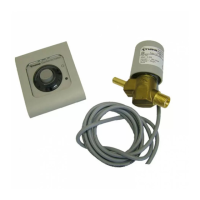
Choose a location for the con-
trol panel (9) at a clearly visible
place.
If it is not possible to install
the control panel flush with
the surface, Truma can provide a
surface-mounting frame (11) on
request, as a special accessory
(part no. 40000-52600).
Drill a 55 mm diameter hole.
Feed the connection cable for
the solenoid valve (6) and 12 V
supply (10) through the hole in
the wall from behind, and con-
nect it to the terminals of the
control panel as shown on the
connection diagram.
1 = white
2 = green
3 = brown
- = Negative pole
+ = Positive pole, 12 V DC
Fit the rear cover flap (14) in
place as a stress-relief arrange-
ment and secure the control
panel (9) with 4 screws (12),
then fit the cover frame (15) in
position.
To round off the appear-
ance of the cover frame,
Truma can provide side pieces
(16) as special accessories in
8 different colours (please ask
your dealer).
Connect appliance to fused
vehicle power supply (central
electrical system 5 – 10 A) us-
ing a cable 2 x 0.75 mm². When
connecting directly to the bat-
tery, always fuse the positive and
negative lead.
Secure all cables with cable
clips.
 Loading...