21
If the control panel cannot
be flush-mounted, Truma
can provide a surface-mounted
frame (11 – part no. 40000-06400)
as an accessory if required.
The scope of delivery
includes a mounting
template and a line-up clip for
mounting several Truma control
panels next to each other.
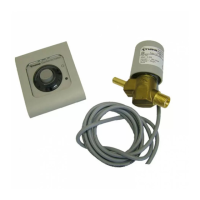
Drill a hole with diameter of
55 mm. Route the connector cable
of the gas remote switch (6) and
the 12 V supply cable (10) from
the back through the hole in the
wall and connect in accordance
with the connecting diagram on
the control panel.
1 2 3
-
+
WH
GN
BN
1 = white
2 = green
3 = brown
- = Negative supply cable
+ = Positive supply cable 12 V DC
Fit the rear blank cover (14) as
strain relief and secure the control
panel (9) with 4 screws (12;not
included). Then attach the cover
frame (15).
Truma supplies side parts
(16) to improve the appear-
ance of the cover frames(15).
Please contact your dealer.
The cable connections
must be laid so that they
cannot chafe or become trapped
by the gas cylinders.
Connect the appliance to the
fused on-board power supply
(central electrical system 5 – 10 A)
with the 2 x 0.75 mm² cable.
If the equipment is connected
directly to the battery, the posi-
tive and negative lines must be
protected.
Incorrect polarity or ca-
bling result in increased
power consumption (>40mA)
and destruction of the gas re-
mote switch.
Secure all cables with cable clips.
When power supply units are
used, it must be ensured that the
output voltage is between 11 V
and 15 V and the alternating cur-
rent ripple is < 1.2 Vss.
 Loading...