Issue 1 – January 2020 Page 12
3.6 ELECTRICAL ASSEMBLY
- PLEASE ENSURE THAT THE BATTERY AND MAINS LEAD ARE BOTH
DISCONNECTED FROM THE RV BEFORE COMMENCING INSTALLATION
The terms right hand and left hand referred to on the electronics control box are
determined by standing in front of the RV (at the hitch) facing the RV for a mover fitted in front
of the wheels.
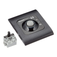
The recommended site for the Electronics Control Box (ECB) is inside the RV in the dry
(bedding) locker behind the battery box. The ECB should be screwed to the floor using the
screws provided. Please note some RVs have under floor cables and/or pipes, checks
must be made to ensure it is safe to drill. If safe to do so then drill four 10mm diameter
holes in the floor approximately 150mm (6 inches) from the control box for the motor wires to
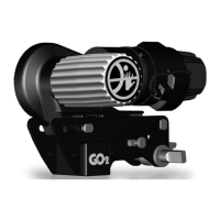
be fed into the RV. Start routing the wires from the motor, remembering to leave a small
amount of slack cable near the motors to allow for their movement when the drive rollers are
engaged. The motor wires (two each) and Powractuator wires (if fitted) can now to be routed
along the underside of the RV floor using the P clips provided (securing of the cables can be
made with a suitable staple gun and the correct size staples – not provided). Care should be
taken to ensure that the cabling is securely fitted so that no chafing can occur and that it does
not sag. Also ensure cables do not make contact with the steel chassis (unless suitable cable
clips are used – not provided). If the Powrtouch is fitted in front of the wheels, then the ECB
should be wired as shown below Fig 6A1. The Powractuation Motors should be wired as
shown in Fig 6F.
Should the Powrtouch Freedom be fitted behind the wheels then the motor wires for Motor 1
(LH) should be wired to M2 and the motor wires for Motor 2 (RH) should be wired to M1. The
polarity of M1 & M2 should be reversed from the positions shown in Fig 6A1.
 Loading...