7
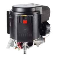
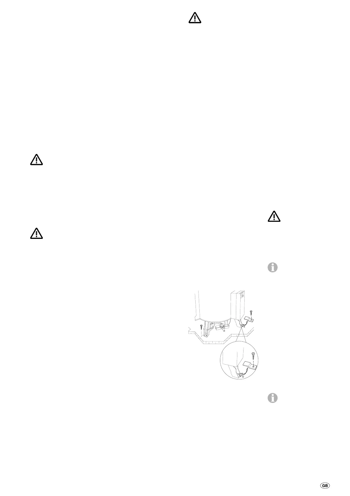
The window switch (special
accessory, part. no. 34000-
85800) is directly connected
to the electronic control unit.
Fig. N: Remove contact
bridge (60) and connect
window switch. The polarity
is not important.
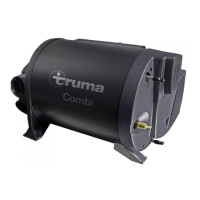
Exhaust duct
For the Trumatic C 6002 EH
only use the Truma exhaust
duct AA 3 (part. no. 39320-00)
or, for boat installation, the
Truma stainless steel exhaust
duct AEM 3 (part no. 39360-
00) and the combustion air
sup ply duct ZR (part no.
39580-00), as the appliance
has only been tested and
approved with these ducts.
The length specifi-
cations refer to the
combusti on air intake duct.
Cut ducts to lengths so that
these project out of the
opening for the cowl during
installation. Cut the exhaust
duct (fig. E: 1) so that it is
10 cm longer. This avoids
elongation and a tension
load on the exhaust duct.
Always install a new
O-ring following any
disassembly.
Permissible duct
lengths
Fig. A 1: For the wall cowl
the duct lengths can be rout-
ed from min. 70 cm to max.
100 cm as ascending duct in
whichever way required, or
descending by max. 5 cm.
Duct lengths of min. 100 cm
to max. 150 cm must be
ascending at an angle of at
least 45°.
Fig. A 2: Roof cowl duct
lengths of up to max. 230 cm
must be ascending at an
angle of at least 45°.
Connection of the
exhaust double duct
to the appliance
Fig. D: Press end of exhaust
duct (1) together so that win-
ding touches winding. Slide
clamp (4) onto connecting
piece (3) and engage. Slide
clamp (7) over the combustion
air supply tube (5). Slide flue
gas pipe (1) over the O-ring (2)
and below the clamp (4), and
tighten clamp (4). Slide com-
bustion air supply tube (5) onto
the connecting piece (6) and
secure with clamp (7).
Assembly of wall cowl
Fig. E: Choose a wall which
is as straight as possible
and which is well exposed
to wind from all directions.
Drill an opening of 83 mm
diame ter (pack wood into
any hol low spaces in the area
of the cowl opening). Use
the en closed rubber seal (8)
for sealing. In the event of
structured surfaces coat with
plastic body sealant – do not
use silicone!
Slide clamp (7) over the
ducts prior to passing the
exhaust double duct through
the opening.
Slide rubber seal (8) and
clamp (4) on the cowl inner
part (9). Press together end
of exhaust duct (1) so that
winding touches winding,
and slide over O-ring (10)
onto the connection fitting
(11 – bend pointing up).
Slide holes of clip (4) onto
pins of muff (11 – screw fac-
ing downwards) and screw
in place. Slide combustion
air intake duct (5) on the ser-
rated connection fitting (12).
Fasten cowl inner part (9)
with 6 self-tapping screws
(14), mount cowl outer part
(15) and fasten with 2 screws
(16).
Fasten combustion air intake
duct with clamp (7), from the
inside, on the connection
fitting (12).
Fasten cowl double duct to
the wall with at least one
clamp ZRS (17).
Assembly of the
roof cowl
Fig. F: Select a part of the
roof which is as straight as
possible and which is well
exposed to wind from all di-
rections. Drill an opening of
83 mm diameter at a center
distance of at least 65 mm
to the side walls (pack wood
into any hol low spaces in the
area of the cowl opening).
Sealing is carried out with
the enclosed rubber seal
(20) without further sealing
compound.
Slide rubber seal (20) on the
cowl part (21). Pass cowl
from above through the roof
and secure with retention
ring (22).
Mount cowl cover (23) and
secure with two screws (24).
The exhaust out lets
(25) must be positioned
crosswise to the direction of
travel, the label „FRONT“
(26) must be facing in the
direction of travel!
Slide clamp (7) over the
exhaust gas double duct.
Press together end of ex-
haust duct (1) so that win ding
touches winding. Slide clamp
(4) onto connecting piece
(28) and engage. Slide clamp
(4) over the combustion air
supply tube (5). Slide flue gas
pipe (1) over the O-ring (27)
and below the clamp (4), and
tighten clamp (4). Slide com-
bustion air supply duct (5) on-
to the connecting piece (29)
and secure with clamp (7).
Fasten cowl double duct
to the wall with at least
3 clamps ZRS (17).
Fastening the
appliance
Bring appliance into installa-
tion position and, using the
three provided fastening
screws B 5.5 x 25, ensure the
appliance is firmly connected
to a suitable base (sawn
wooden board, laminated
wooden battens or metal
base).
Within limited installation
space, the provided „Z“-
bracket can be used to
fasten the appliance under
the electronic housing.
Warm air distri bu tion
and circulating air
return
Heating air intake vents must
be arranged in such a way
that under normal operating
conditions exhaust gas from
the vehicle engine and heater
appliance cannot enter the
inside of the vehicle. It must
be ensured by means of
construction design that the
heating air introduced into
the vehicle is not polluted
(e.g. by oil vapour). This is
achieved, for example, with
air heaters with circulating
air operation, both for interior
installations and for external
installations. (In heaters with
fresh air operation the fresh
air is not to come from the
engine compartment or from
the vicinity of the exhaust
or the exhaust outlet of the
heater.)
Warm air distribution
Most of the warm air is led
into the floor area of the
living compartment via
flexible warm air ducts.
The 4 connecting pieces on
the unit are designed for the
65 mm diameter ÜR duct
(part. no. 40230-00). Only
pressure-proof air ducts that
comply with the Truma qual-
ity standard must be used.
Other ducts that do not meet
our quality standard (particu-
larly with regard to crown
pressure resistance, ducts
diameter and number of
grooves) must not be used.
In order to prevent
heat accumulation, all
4 warm air connecting
pieces must be connected
up. The cross-section of the
warm air ducts must not be
reduced by connections or
the like.
If an EN end outlet that
can be closed off is in-
stalled in one of the Trumatic
C 6002 EH warm air ducts
(e.g. in the bathroom), a se-
cond outlet that cannot be
closed off must be installed
in the warm air duct.
The warm air system is de-
signed for each type of vehi-
cle individually, on a modular
basis. There is an exten-
sive accessories program
available (refer here to our
brochure). You can obtain
diagrams free of charge from
the Truma Service Centre,
showing optimal installation
suggestions for warm air
systems in all current-type
caravans and mobile homes.
By using the 72 mm
diameter VR duct up to
the respective first air out-
let, the amount of noise is
reduced. Remove reducing
sleeves from air outlet con-
nections and use U-clamp
set (part no. 34000-81800)
when connecting this pipe.
 Loading...