23
ACS-100 Free Movement Adjustable Cable System
Step 11 Routing one of the Crossover Cables to the Left Side of the Unit
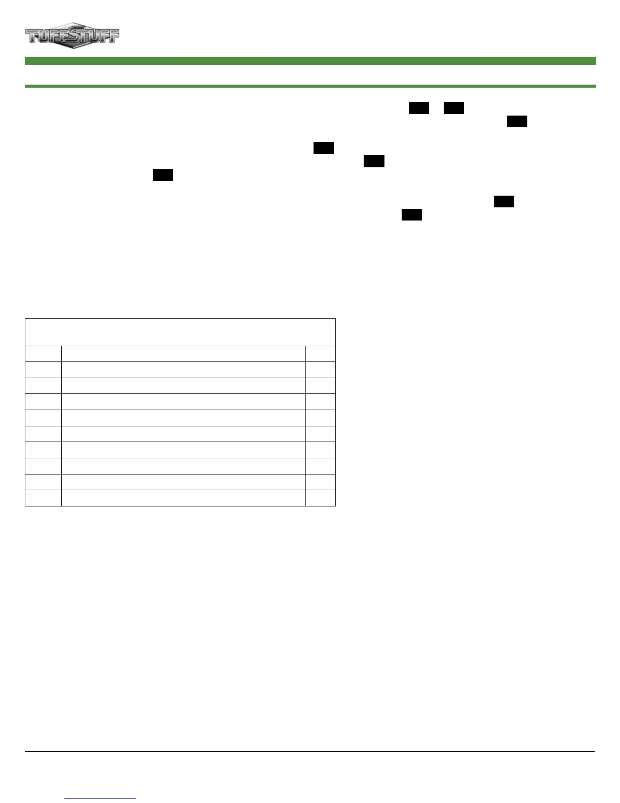
Assembly List
Item # Description Qty.
29 CROSSOVER CABLE 1
41 FINISHED HEX NUT B/O 1/2-13 1
63 NYLON BALL 1 3/4 X 5/16 1
64 NYLON D HANDLE (# H834A) 1
67 NYLON INSERT LOCK NUT B/O 5/16-18 1
88 SHOULDER BOLT ALLOY 3/8 X 3/4 1
91 SPLIT HEX TAP BOLT GR-5 B/O 1/2-13 X 3 1/2 1
92 SPLIT LOCK WASHER B/O 1/2” 1
95 STRAP BRACKET 20 #SF20 STAINLESS STEEL 1
A. Route the Crossover Cable (#29) between Nylon Pulleys (#71-Labeled
B1
&
B2
). Next, route through the
tube of the High/Low Double Pulley Brkt (#16) and down to the Nylon Pulley (#71-Labeled
B3
).
B. Route the cable under the Nylon Pulley (#71-Labeled
B4
) then up to the Closed End Adjustable Pulley Brkt
(#24) and route the cable over the Nylon Pulley (#71-Labeled
B5
). Next, route down and under the Nylon
Pulley (#71-Labeled
B6
).
C. Route up to the Guide Rod Retainer (#14) passing over the Nylon Pulley (#71-Labeled
B7
) and under the
Cable Retainer (#25). Next, route over the Nylon Pulley (#71-Labeled
B8
).
D. Route the cable to the threaded socket of the Carriage (#15). Secure the Cable (#29) to the Carriage (#15)
using one Split Hex Tap Bolt 1/2-13 X 3 1/2 (#91), one Finished Hex Nut 1/2-13 (#41), and one Split Washer
1/2” (#92).
E. Assemble one of the Nylon D Handles (#64) to the Cable (#29) using hardware shown.