Do you have a question about the Turbo Air TGF-9F and is the answer not in the manual?
Visual identification of components on the front of the TGF-23F model.
Visual identification of components on the side of the TGF-23F model.
Visual identification of components on the front of the TGF-49F model.
Visual identification of components on the side of the TGF-49F model.
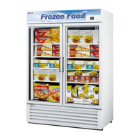
Visual identification of components on the front of the TGF-72F model.
Visual identification of components on the side of the TGF-72F model.
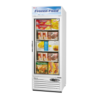
Visual identification of components on the front of the TGF-9F and TGF-13F models.
Visual identification of components on the side of the TGF-9F and TGF-13F models.
Visual identification of components on the rear of the TGF-9F and TGF-13F models.
Detailed breakdown and labeling of door assembly components for the TGF-23F model.
Exploded view and part identification for the right door assembly of TGF-49F and TGF-72F.
Exploded view and part identification for the left door assembly of TGF-49F and TGF-72F.
Identification of ductwork components within the TGF-23F model.
Identification of ductwork components within the TGF-72F model.
Electrical schematic illustrating the wiring configuration for the TGF-9F model.
Electrical schematic illustrating the wiring configuration for the TGF-13F model.
Electrical schematic illustrating the wiring configuration for the TGF-23F model.
Electrical schematic illustrating the wiring configuration for the TGF-49F model.
Electrical schematic illustrating the wiring configuration for the TGF-72F model.
Technical details and part numbers for compressors used in various models.
Identification of compressor relay and overload protection components.
List of compressor starting and running capacitor specifications and part numbers.
Details on condenser fan motor specifications, including part numbers and manufacturers.
Details on evaporator fan motor specifications, including part numbers and manufacturers.
Information on thermostat and evaporator defrost heater specifications and part numbers.
Specifications and part numbers for ballasts, fluorescent lamps, and LED components.
Details on various switch types, including part numbers and ratings.
Identification of transformer and main PCB components with specifications.
Guide on using the display panel, including button functions and display indicators.
Comprehensive table detailing control functions, objects, and their operational contents.
Table outlining error codes, perception methods, and freezer operation states during malfunctions.
Description of F-sensor and D-sensor, including operation, wire color, and purpose.
Catalog of castor, compressor, and condenser parts with model applicability.
Catalog of glass components, including front and door glass, with model applicability.
Catalog of sign panel, grille, thermostat, and PCB parts with model applicability.
Procedure for removing the bottom grille and display PCB on the TGF-23F model.
Steps for disconnecting connectors and replacing power/lamp switches on TGF-23F.
Steps for replacing fixtures, ballasts, main PCB, transformer, and power relay for TGF-23F.
Instructions for disconnecting door wires and removing the sign frame for door replacement.
Procedure for removing the sign panel from the TGF-23F model.
Procedure for removing door switch harness and door hinge top on TGF-23F.
Steps for removing bottom grille and replacing the condensing unit for TGF-49F/72F.
Procedure for replacing SMPS and electrical box components on TGF-49F/72F.
Instructions for replacing ballast and power relay components on TGF-49F.
Procedure for replacing the ballast component on the TGF-49F model.
Steps for removing and replacing components within the advertising panel for TGF-49F/72F.
| Model | TGF-9F |
|---|---|
| Type | Freezer |
| Capacity | 9 cu. ft. |
| Number of Doors | 1 |
| Shelves | 3 |
| Refrigerant | R-290 |
| Defrost Type | Automatic |
| Door Type | Glass |
| Power Supply | 115V, 60Hz |
| Certification | ETL |
| Horsepower | 1/2 HP |