Do you have a question about the Turbo LEVO SL and is the answer not in the manual?
Provides information on written warranty provisions and where to find them.
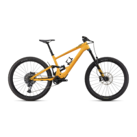
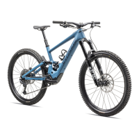
Details the intended purpose and riding conditions for the Turbo Levo SL bicycle.
Explains the classification as an EPAC and legal/regulatory considerations for use.
Provides advice for optimal riding experience, component wear, and battery range.
Lists essential checks and familiarization steps before riding the bicycle.
Guidance on calculating and managing the electric bicycle's riding range.
Instructions on locating and using the bicycle's serial number sticker.
Safety precautions and considerations for riding with children or accessories.
Details specifications and installation guidance for headset bearings.
Explains seatpost minimum/maximum insertion and fitting guidelines.
Instructions for installing the SRAM UDH derailleur hanger.
Details the speed sensor magnet, its location, and maintenance.
Procedure for setting the chain guide position.
Guidance on installing the Alloy Trail Stem and headset compression.
Step-by-step instructions for handlebar installation with torque specifications.
Ensuring adequate clearance between handlebar, stem, and TCU.
Instructions for fitting and removing the carbon rock guard.
Instructions for fitting and removing the alloy rock guard.
Procedure to check and resolve tire interference with the saddle.
Information on obtaining genuine replacement parts and accessories.
Situations requiring the bicycle system to be powered OFF to avoid unintentional motor engagement.
Overview of the Turbo Control Unit (TCU) display and its components.
Details the MasterMind TCU display, its features, and customization options.
Instructions on how to power on and off the bicycle system.
Description of the TCU handlebar remote and its controls.
Explanation of the functions of the TCU remote buttons.
Description of the MasterMind TCU handlebar remote and its controls.
Explanation of the functions of the MasterMind TCU remote buttons.
Overview of the different motor assist modes available on the TCU and MasterMind TCU.
Instructions on how to cycle through support modes using the TCU remote.
Guide to changing support modes on the MasterMind TCU via the remote.
Explanation of the Micro Tune mode for adjusting support and peak power.
Steps for customizing the MasterMind TCU display and settings.
Options for customizing display pages, layouts, and data fields.
Details Bluetooth and ANT+ connectivity for the bicycle system.
Features for automatically recording rides using the Specialized app.
Explanation of TCU error codes and troubleshooting solutions.
Explanation of MasterMind TCU error messages and troubleshooting.
Procedure for performing standard and factory resets on the system.
Instructions for replacing the coin-cell battery in the TCU.
Overview of app features: motor tune, connected ride recording, and smart control.
Steps for creating an account or signing in to the Specialized app.
Information on accessing in-app help for features and terms.
Instructions for connecting your bicycle to the Specialized app.
Crucial safety precautions regarding fire and electric shock risks.
Identification of physical damage signs and immediate actions for damaged batteries.
Guidance on removing and replacing the bicycle's internal battery.
General guidelines for operating the battery and charger.
Step-by-step instructions for safely charging the bicycle battery.
How to read the battery charge status on the TCU and MasterMind TCU.
Guidelines for cleaning the battery and bicycle components.
Specific procedures for cleaning the battery and charge port area.
Troubleshooting steps for when the bike does not power on.
Recommendations for transporting and storing the bicycle and battery.
Safety precautions for shipping and transporting the battery.
Guidelines for storing the bicycle and battery for extended periods.
Information on proper disposal of batteries and electronic components.
Technical specifications for the bicycle's battery models.
Technical specifications for the bicycle's charger.
Lists key specifications for various bicycle components and parts.
Guidance on selecting compatible shocks and potential compatibility issues.
Information on bolt sizes, required tools, and critical torque specifications.
Details specifications for bearings and spacers used in the bicycle's pivots.
Lists specifications for various bolts and axles used in the bicycle assembly.
Torque specifications for various suspension pivot bolts.
Explains how flip chips and headset cups alter geometry and handling.
Presents standard geometry measurements for different configurations.
Procedure for adjusting the head tube angle using headset cups.
Procedure for adjusting bottom bracket height using shock extension flip chips.
Instructions for adjusting rear wheel size using Horst pivot flip chips.
Steps for setting correct air pressure in the suspension shock.
Guidance on adjusting rebound damping for optimal suspension performance.
How to adjust compression damping for shock absorption.
Instructions for installing the UDH derailleur hanger assembly.
Instructions for installing and using the Range Extender (RE).
Explanation of battery discharge modes when using the Range Extender.
Procedures for charging the Range Extender, including Y-cable use.
How the MasterMind TCU displays charge level with an RE connected.
| Chain | SRAM GX Eagle, 12-speed |
|---|---|
| Chainrings | 32T |
| Motor | Specialized SL 1.1 |
| Motor Power | 240W |
| Battery | Specialized SL1-320, 320Wh |
| Range | Up to 80 miles |
| Charging Time | Approx. 2.5 hours |
| Frame | FACT 11m carbon |
| Fork | 150mm travel |
| Rear Shock | 150mm travel |
| Drivetrain | 12-speed |
| Brakes | SRAM, 4-piston caliper, hydraulic disc |
| Tires | Butcher, GRID TRAIL casing, GRIPTON compound, 2Bliss Ready, 29x2.3" |
| Display | Specialized TCU |
| Charger | Specialized 4A Charger |
| UI/Remote | Specialized TCU |
| Rear Derailleur | 12-speed |
| Shifters | 12-speed |
| Cassette | SRAM XG-1275 Eagle, 12-speed, 10-52t |
| Wheelset | Roval Traverse Carbon, 29" |
| Front Tire | Butcher, GRID TRAIL casing, GRIPTON compound, 2Bliss Ready, 29x2.3" |
| Rear Tire | Butcher, GRID TRAIL casing, GRIPTON compound, 2Bliss Ready, 29x2.3" |
| Saddle | Bridge Comp, Hollow Cr-mo rails |
| Seatpost | 34.9mm |