DE
Kurzbetriebsanleitung
In Betrieb nehmen
Nach Anschluss der Leitungen und Aufschalten der Versorgungsspannung geht das Gerät
automatisch in Betrieb.
Betreiben
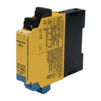
LED-Anzeigen
LED Farbe Bedeutung
Pwr grün Gerät ist betriebsbereit
blinkt grün Force-Modus im DTM aktiv
rot Gerätefehler oder Eingangsfehler
1 gelb Schaltzustand: Relais angezogen
2 gelb Schaltzustand: Relais angezogen
3 gelb Schaltzustand: Relais angezogen
Einstellen und Parametrieren
Die Geräte können über FDT und DTM mit einem PC parametriert werden. Zusätzlich ist eine
Basisparametrierung über Taster am Gerät sowie über die Stromschnittstelle mit HART-Proto-
koll möglich. Weitere Informationen entnehmen Sie der Parametrieranleitung.
Reparieren
Das Gerät ist nicht zur Reparatur vorgesehen. Defekte Geräte außer Betrieb nehmen und zur
Fehleranalyse an Turck senden. Bei Rücksendung an Turck beachten Sie bitte unsere Rücknah-
mebedingungen.
Entsorgen
Die Geräte müssen fachgerecht entsorgt werden und gehören nicht in den normalen
Hausmüll.
FR
Guide d’utilisation rapide
Mise en service
L'appareil se met automatiquement en marche après le raccordement des câbles et l'activation
de la tension d'alimentation.
Fonctionnement
Achage LED
LED Couleur Signication
Pwr Verte L'appareil est opérationnel
Verte clignotante Mode Force du DTM activé
Rouge Erreur d'appareil ou erreur d'entrée
1 Jaune État de commutation: relais enclenché
2 Jaune État de commutation: relais enclenché
3 Jaune État de commutation: relais enclenché
Réglages et paramétrages
Les appareils peuvent être paramétrés sur un PC via FDT et DTM. De plus, il est possible d'effec-
tuer un paramétrage de base via un bouton sur l'appareil ou via la boucle de courant avec
protocole HART. Pour plus d'informations, consultez les instructions de paramétrage.
Réparation
L'appareil ne peut pas être réparé. Si l'appareil est défectueux, mettez-le hors service et ren-
voyez-le à Turck pour un diagnostic des défauts. En cas de retour à Turck, veuillez respecter les
conditions de reprise.
Mise au rebut
Les appareils doivent être mis au rebut de manière appropriée et ne peuvent être jetés
avec les ordures ménagères.
EN
Quick Start Guide
Commissioning
The device is operational automatically once the cables are connected and the power supply is
switched on.
Operation
LED indication
LED Color Meaning
Pwr Green Device is operational
Green flashing Force mode in the DTM active
Red Device error or input error
1 Yellow Switching state: Relay energized
2 Yellow Switching state: Relay energized
3 Yellow Switching state: Relay energized
Setting and parameterization
The devices can be configured with a PC via FDT and DTM. A basic configuration can also be
set by pushbuttons on the device as well as with the HART protocol via the current interface.
Further information is provided the parameterization instructions.
Repair
The device is not intended for repair. Take defective devices out of operation and send them to
Turck for fault analysis. Observe our return acceptance conditions when returning the device
to Turck.
Disposal
The devices must be disposed of correctly and must not be included in general house-
hold garbage.
Hans Turck GmbH & Co. KG | Witzlebenstraße 7, 45472 Mülheim an der Ruhr, Germany | Tel. +49 208 4952-0 | Fax +49 208 4952-264 | more@turck.com | www.turck.com © Hans Turck GmbH & Co. KG | 100002576 2023-06
IM33-14EX-CDRI
Ex ia IIC IIB
L
O
max. 0.15 mH 0.3 mH 0.15 mH 1 mH 5 mH
C
O
max. 50 nF 30 nF 950 nF 680 nF 630 nF
Approvals and markings
Approvals
IBExU07 ATEX 1156 X
ÉII (1) G [Ex ia Ga] IIC
ÉII (1) D [Ex ia Da] IIIC
ÉII (1) 3G Ex ec nC [ia Ga] IIC T4 Gc
ÉII (1D) 3G Ex ec nC [ia Da IIIC] IIC T4 Gc
IECEx IBE 09.0007 X [Ex ia Ga] IIC
[Ex ia Da] IIIC
Ex ec nC [ia Ga] IIC T4 Gc
Ex ec nC [ia Da IIIC] IIC T4 Gc
模拟量输入安全栅
Permissible ambient temperature range T
amb
: -25…+70 °C
Certication data
Electrical data
Supply circuit
non intrinsically safe
Contacts 19 and 20 U
B
= 20…250 VAC
or 20…125 VDC
U
m
= 253 VAC/125 VDC
Sensor current circuits
intrinsically safe
Ex ia IIC/IIB
Contacts 1…4 Maximum values:
U
0
= 21.6 V
I
0
= 85 mA
P
0
= 459 mW
Characteristic curve: trapeziodal
R
i
= 408 Ω
C
i
= negligible
L
i
= negligible
U
i
= 40 V
P
i
= 600 mW
Output circuit
non intrinsically safe
Contacts 11 and 16 U = 13.5 VDC
I = 22.5 mA
Contact circuit
non intrinsically safe
Contacts 12 and 13
Contacts 14 and 15
Contacts 17 and 18
U = 250 VAC, I = 2 A,
P = 500 VA/60 W
U = 120 VDC, I = 0.5 A
U = 30 VDC, I = 2 A
Conguration interface
non intrinsically safe
Front side stereo jack U = 3.3 V
⑥
7 mm
0.2…2.5 mm
2
(24…13 AWG)
1
2
0.5 Nm
(4.43 LBS-inc)
⑦
7 mm
0.2…2.5 mm
2
(24…13 AWG)
1
2
⑧
3 mm≥ 6 mm≥ 50 mm
546
213
Pwr
1110 12
879
1
546
213
Pwr
1110 12
879
12
1816 17
Pwr
2019
1311 12 1514
867 109
312 54
Wiring diagram
IM33-14EX-CDRI
 Loading...