EasyManua.ls Logo

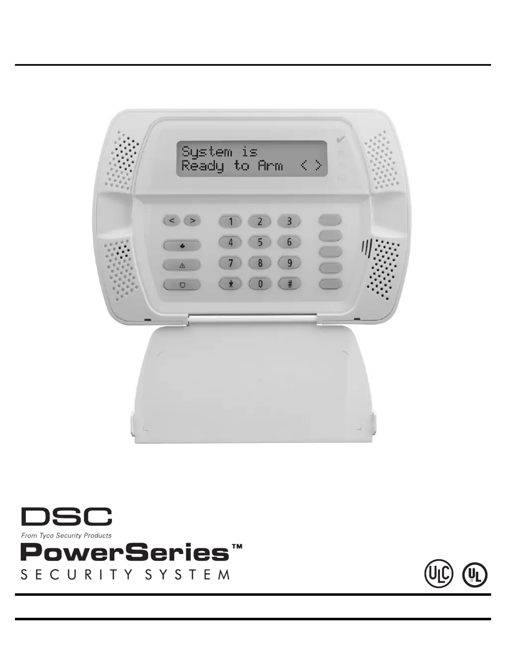
Tyco Security Products DSC Power Series - User Manual

Tyco Security Products DSC Power Series
68 pages
Print Icon
To Next Page IconTo Next Page
Loading...
Self Contained Wireless Alarm System
v1.0 Installation Guide
WARNING: This manual contains information on limitations regarding product use and function and
information on the limitations as to liability of the manufacturer. The entire manual should be carefully read.

Questions and Answers

  • S
    Scott Reyes Jr.Aug 16, 2025
    How to fix low battery on Tyco Security Products DSC Power?
    • J
      jfoleyAug 16, 2025
      If the main panel battery is less than 7.2VDC, and you get a low battery warning, give a new battery 24 hours to charge. Check that the voltage across the AC terminals is between 16-18 VAC, and replace the transformer if needed. You may also try disconnecting and reconnecting the battery leads.
  • S
    Steven WalterAug 22, 2025
    What to do if my Tyco Security Products DSC Power Security System fails to communicate?
    • I
      Ian ThomasAug 22, 2025
      If the panel fails to communicate events to the central station, connect a headset to the TIP and RING of the control panel to check for a continuous dial tone, reversed TIP and RING, or a recorded operator message. Verify the correct phone number is programmed and that the number can be dialed using a regular telephone. Ensure the programmed format is supported by the central station and that the account number and reporting codes are correctly programmed. For Contact ID and Pulse formats, program a HEX [A] to transmit a digit [0] in SIA format, or program a digit [0] to transmit a digit [0].
  • J
    Jennifer TorresAug 25, 2025
    Why does my Tyco Security Products Security System show a general system trouble?
    • A
      Amanda GuerreroAug 26, 2025
      A general system trouble on your Tyco Security Products Security System indicates either an RF Jam has been detected for 20 seconds or communication with the wireless receiver has failed, causing a Hardware Fault. Check the Event buffer to determine the specific trouble. If the buffer logs an RF Jam trouble, check for external 433MHZ signal sources. To disable RF Jam, enable Option [7] in program section [804] subsection [90]. If the Buffer logs a Hardware fault, replace the panel.
  • R
    Robert MartinAug 28, 2025
    How to troubleshoot telephone line trouble on Tyco Security Products Security System?
    • J
      Jesse ThomasAug 28, 2025
      If the phone line voltage at TIP, RING on the main panel is less than 3VDC, measure the voltage across TIP and RING on the panel. With no phone off-hook, it should be approximately 50VDC; with any phone off-hook, it should be approximately 5VDC. Try wiring the incoming line directly to TIP and RING. If the trouble clears, check the wiring or the RJ-31x phone jack.
  • H
    hartjeremiahAug 31, 2025
    What to do if my Tyco Security Products DSC Power Security System reports a zone fault?
    • K
      Kenneth PetersAug 31, 2025
      If a hard-wired zone fault condition is present, and a short circuit exists on one or more zones with double end-of-line resistors enabled, remove the wire leads from the I/O and COM terminals and measure the resistance of the wire leads. Then, connect a 5.6K resistor (Green, Blue, Red) across the I/O and COM terminals to see if the trouble condition clears. Alternatively, if one or more wireless devices have not checked in within the programmed time, perform a Module Placement Test – Program Section [904] to verify the wireless device is in a good location. If bad test results occur, test the wireless device in another location. If the wireless device continues to give bad test results, replace the wireless device.
  • J
    Jessica VargasSep 3, 2025
    How to resolve a zone tamper issue on my Tyco Security Products DSC Power?
    • D
      debraweissSep 3, 2025
      If an open circuit is present on one or more zones with double end-of-line resistors enabled, remove the wire leads from the I/O and COM terminals and measure the resistance of the wire leads. Connect a 5.6K resistor (Green, Blue, Red) across the I/O and COM terminals and verify the trouble condition clears. If a tamper condition is present on one or more wireless devices, ensure the device cover is secure and the device is correctly mounted for wall tamper operation. Violate, then restore the tamper; if the tamper condition persists, replace the wireless device.
  • S
    Sandra MckeeSep 6, 2025
    How do I fix a wireless device low battery on Tyco Security Products DSC Power Security System?
    • N
      Nathaniel GarciaSep 6, 2025
      If one or more wireless devices has a low battery, replace the battery. Then, verify zone operation and confirm that the tamper and low battery condition is cleared and reported. Replacing batteries will cause a tamper. Replacing the cover will restore the tamper causing the associated reporting codes to be sent to the Central Station.
  • R
    Robert BentleySep 9, 2025
    What causes a general system tamper on Tyco Security Products DSC Power Security System?
    • T
      Travis KhanSep 9, 2025
      A general system tamper is tripped when the cover tamper is activated. To resolve this, verify that the tamper button is installed into the back plate and that the keypad (cover) is secured to the backplate.
  • B
    Brandy StephensSep 10, 2025
    What to do if my Tyco Security Products Security System has AC failure?
    • R
      Richard DanielsSep 12, 2025
      If there is no AC at the panel AC input terminals, verify the voltage measured across the AC terminals is 16-18VAC. If it is not, replace the transformer.
  • D
    Donald BautistaSep 12, 2025
    How to reset clock/date on Tyco Security Products DSC Power?
    • A
      Amy McphersonSep 12, 2025
      If the main panel internal clock is not set, program the time and date by entering [*][6][Master Code] then Press [1]. Enter the time and date (in military) using the format HH:MM MM/DD/YY. For example, for 6:00 pm, Nov. 30, 2007, enter: [18] [00] [11] [30] [07].

Summary

Safety Instructions for Service Personnel

Before Installing The Equipment

Ensure your package includes the following items and read all instructions before proceeding.

Selecting A Suitable Location For The Alarm Controller

Guidelines for choosing a suitable and safe location for the alarm controller.

Safety Precautions Required During Installation

Essential safety measures to follow during the installation process.

Section 1: Installation & Wiring

Important Installation Notes

Critical notes regarding installation environment and power supply.

1.1 Installation Procedures

Important Pre-Power Installation Steps

Crucial steps to ensure wiring is complete before applying power.

Device Enrollment Process

Procedure for enrolling wireless devices into the system.

1.2 Wiring Guidelines

Zone Wiring Configuration

Guidelines for wiring zones using SEOL or DEOL resistors.

PGM;Aux Power Wiring

Instructions for connecting PGM and Aux Power wiring.

Telephone Line Wiring

Procedure for connecting the telephone line to the system.

Battery Information

AC Wiring Requirements

Section 2: Wireless Device Enrollment

Enrollment Process Steps

Steps to enter mode, activate, verify ESN, and assign zone number.

Section 3: Template Programming

Template Programming Data Entry

Configure Communication & Access Details

Enter phone numbers, account codes, DLS access, delays, and installer code.

Section 4: DLS Programming

4.1 Local Programming with PC-Link

Steps for setting up local programming using a PC-Link cable.

4.2 Remote Programming (via telephone line)

Information on remote programming via telephone line.

Section 5: Operation

Arming and Disarming Modes

Procedures for Away, Stay, Disarming, and related zone functions.

Keypad Command Functions

Description of [*] commands, bypass, and other keypad functions.

System Status and User Management

Advanced System Functions and Controls

System and Installer Functions

Accessing user functions, installer programming, and command outputs.

Section 6: Advanced Programming

How to Program

General guidelines and recommended steps for programming.

Programming Toggle Options

How to program options that toggle between ON and OFF.

Programming Decimal and Hexadecimal (HEX) Data

How to enter data in decimal and hexadecimal formats.

How to Exit Installer Programming

Procedure for safely exiting installer programming.

Section 7: Programming Work Sheets

[001]-[002] Zone Definitions

Core System Configuration Settings

System Option Groups

Zone and Communication Configuration

Zone Settings and Attributes

Configuring zone loop response and attributes.

System Timing and Zone Assignment

Zone Assignment Configuration

Activating and assigning system zones.

Reporting Codes Configuration

[320]-[322] Alarm Reporting Codes

Worksheet for alarm reporting codes for each zone.

[324]-[326] Alarm Restoral Reporting Codes

Worksheet for alarm restoral reporting codes for each zone.

Tamper and Closing;Opening Reporting Codes

Maintenance and Test Transmission Reporting Codes

Communicator Format and Call Direction Options

Communication Settings and Variables

DLS Downloading and Communicator Options

[501]-[502] PGM Output Attributes

Advanced System Features and International Settings

[804] Wireless Programming

Wireless Zone Programming

Worksheet for entering serial numbers for wireless zones.

Wireless Key Programming

Worksheet for entering serial numbers for wireless keys.

Wireless System Management and Installer Functions

Keypad Programming and System Labels

Keypad Display and Zone Chime Configuration

Section 8: Programming Descriptions

[101]-[134] Zone Attributes

Description of zone attributes and customization options.

Core Programming Descriptions

[013] First System Options Description

[014] Second System Options Description

[015] Third System Options Description

[016] Fourth System Options Description

[023] Tenth System Options Description

[030] Zone Loop Response Options Description

[101]-[134] Zone Attributes Description

System Timing and Zone Configuration Descriptions

[301]-[303] Communication Telephone Numbers

[310] System Account Number

[320]-[348] Reporting Codes

[074] First Keypad Options

[075] Second Keypad Options

Section 9: Testing & Troubleshooting

System Testing Procedures

Steps for testing the alarm system after installation.

General Troubleshooting Guidance

General troubleshooting steps and guidance.

System Troubleshooting Guide

Appendix E: 2-Way Audio Verification (SCW9047 only)

Tyco Security Products DSC Power Series Specifications

General IconGeneral
Wireless CompatibilitySupports wireless sensors (requires compatible receiver)
Power Supply16.5VAC, 25VA
Battery Backup12VDC, 4Ah
Output Current500mA
Operating Temperature32°F to 120°F (0°C to 49°C)

Related product manuals