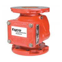
TFP910
Page 4 of 22
SCREEN
ORIFICE
ORIFICE
WITH 0.125" (3.2 mm)
DRAIN RESTRICTION
WITH 0.219" (5.6 mm)
INLET RESTRICTION
Technical
Data
Approvals
UL and C-UL Listed, as well as FM
Approved
Working Water Pressure Range
20 to 300 psi (1,4 to 20,7 bar)
Friction Loss
Refer to Graph A.
Physical Characteristics
The body is ductile iron, the hand-hole
cover is ductile iron, and the seat ring
is bronze. The clapper for the 2-1/2
inch (DN65) valve size is stainless
steel. The clapper for the larger valve
sizes is ductile iron. All valve sizes uti-
lize an EPDM clapper facing.
Flanged connections are available
drilled per ANSI, ISO, AS, and JIS
specifications as detailed in Table A.
Threaded port connections for the AV-
1-300 Valves are available NPT thread-
ed or threaded per ISO 7/1 as detailed
in the Ordering Procedure section.
Valves with NPT threaded ports will
readily accept the trim arrangements
detailed in Figures 4 through 6.
Operation
When the fire protection system is in-
itially pressurized, water flows into
the system until the water supply and
system pressure become equalized,
and the torsion Spring closes the Wa-
terway Clapper in the Alarm Check
Valve. Once the pressures stabilize,
the Alarm Check Valve is in service
and the centrally located groove in
the Seat Ring is sealed. Consequent-
ly, with the Alarm Check Valve set for
service, there is no flow through the
alarm port to the alarm devices (that
is, water motor alarm and/or pressure
alarm switch).
When there is a steady flow of wa-
ter into the sprinkler system due to
a sprinkler operation, the Waterway
Clapper opens as shown in Figure 2.
Water is then permitted to flow into
the centrally located groove in the
Seat Ring and out through the alarm
port towards the Re striction Assembly
(Figure 3). When the flow through the
Inlet Restriction of the Restriction As-
sembly exceeds the flow through the
Outlet Restriction, the Retard Cham-
ber (where provided for systems with
variable pressure), begins to fill.
Subsequently, the Water Motor alarm
and/or the pressure alarm switch will
be actuated. The alarms will continue
to be actuated as long as the Water-
way Clapper remains open. Water in
the alarm lines will automatically drain
out through the 1/8 inch (3,2 mm)
Drain Orifice in the Restriction As-
sembly (Figure 3) when the Waterway
Clapper closes (due to a discontinua-
tion in the flow of water into the sprin-
kler system).
For variable pressure systems, slow
as well as small transient increases in
water supply pressure may continue to
build up in the system (via the Bypass
Check Valve) without opening the Wa-
terway Clapper.
A transient surge in supply pressure
that is sufficient only to open the Wa-
terway Clapper momentarily will not
cause a false alarm, and a portion
of the increase in pressure will be
trapped within the system, thus re-
ducing the possibility of another open-
ing. Any water in the alarm line is au-
tomatically drained, further reduc ing
the possibility of a false alarm due to
a successive transient surge in sup ply
pressure.
FIGURE 2
2-1/2, 4, 6 & 8 INCH (DN65, DN100, DN150 & DN200)
MODEL AV-1-300 ALARM CHECK VALVE
— OPERATION —
FIGURE 3
RESTRICTION ASSEMBLY
(Provided with Alarm Check Valve Trim)
PRESSURE
WATERFLOW
ALARM SWITCH
MOTOR ALARM
VALVE
RESTRICTION
(3,2 mm)
OUTLET
ORIFICE
RETARD CHAMBER
BEGINS TO FILL
INLET EXCEEDS OUTLET,
RESTRICTION ASSEMBLY
WHEN FLOW THROUGH
ASSEMBLY
1/8"
CHAMBER
RETARD
INLET
ALARM PORT
RING GROOVE AND
THROUGH SEAT
WATERFLOW
MAIN
DRAIN
ALARM ACTUATE
WATERFLOW PRESSURE
CHAMBER OVERFLOWS,
ONCE RETARD
WATER MOTOR
ALARM SWITCH AND
WATERFLOW
TO SYSTEM
WATERFLOW
TO WATER
7/32"
ORIFICE
(5,6 mm)
UPON SPRINKLER
FLOW, WATERWAY
CLAPPER OPENS
GAUGE
GAUGE
SUPPLY
PRESSURE
PRESSURE
SYSTEM
CHECK
VALVE
ALARM

 Loading...