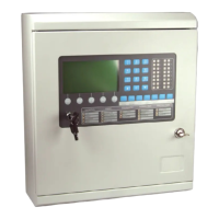
MZX 125/250 Fire Detection Systems
14 Doc. version 1
3.1.3 CONTROL CONTROL MODULE
The Display Control Module contains the following indicators and controls:
INDICATORS
GENERAL
A red Fire LED.
A yellow Fault LED.
A yellow Disabled LED.
A yellow Test LED.
PANEL
A green Power ON LED.
A yellow LED to indicate Mains Fault.
A yellow LED to indicate System Fault.
A yellow LED to indicate Day Mode.
SOUNDER
A red Activated LED.
A yellow Fault LED.
A yellow Disabled LED.
SIGNALLING
A red Activated LED.
A yellow Fault LED.
A yellow Disabled LED.
PROTECTION
A red Activated LED.
A yellow Fault LED.
A yellow Disabled LED.
ZONES
One red (Fire) and one yellow (Fault) LED per zone .
SWITCHES
‘ENABLE’ keyswitch - a two position keyswitch, with positions
‘normal’ and ‘enable’.
Seven control switches:
‘SILENCE BUZZER’ - used to silence the internal buzzer.
‘SILENCE/RESOUND’ - used to silence/resound external
sounders.
‘RESET’ - used to reset the system after an alarm or event has
occurred.

 Loading...