Assembly
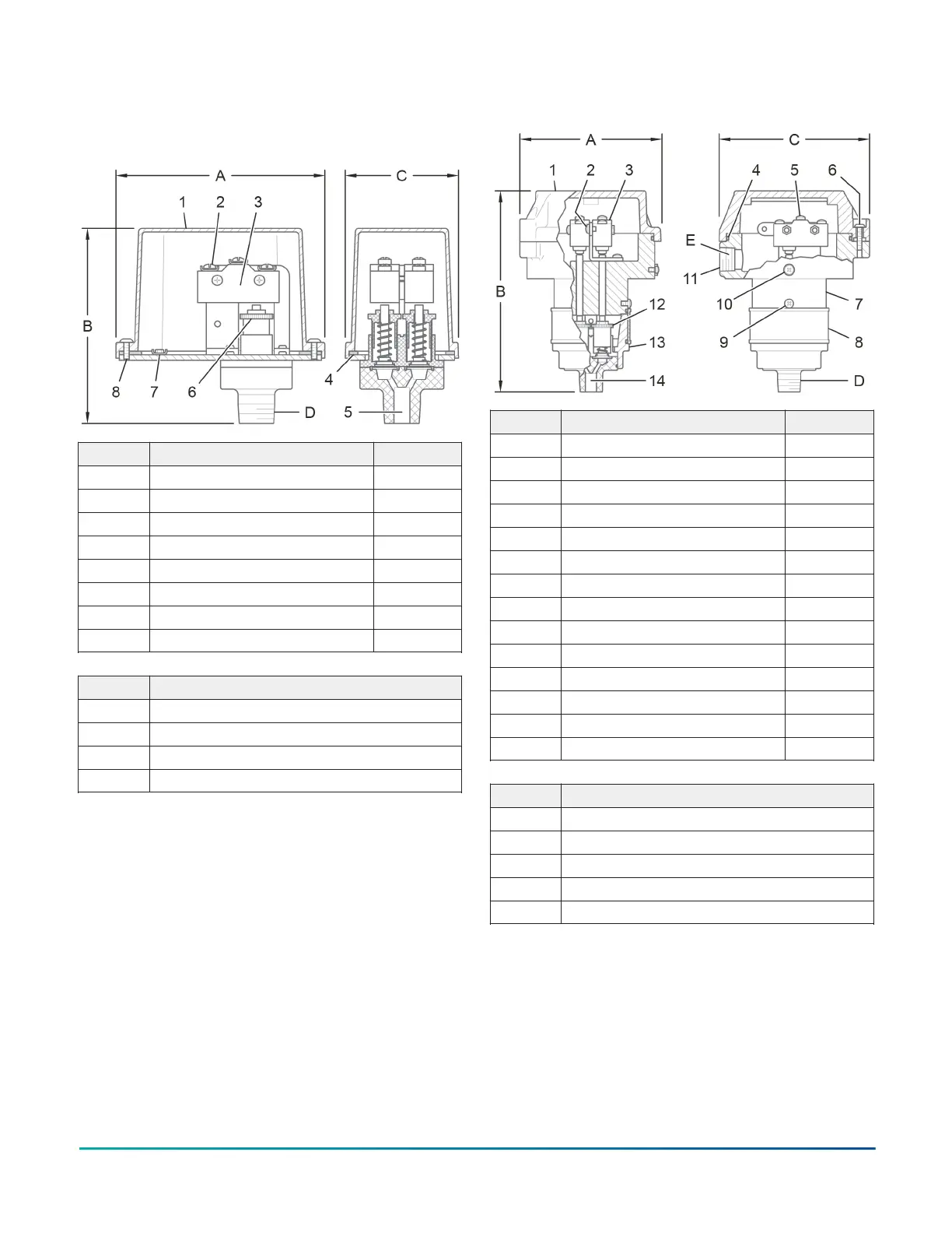
Figure 1: Standard models, components and
dimensions
Callout Component Quantity
1 Cover 1
2 Electric signal terminal 1
3 Switch 1
4 Cover gasket 1
5 Inlet port 1
6 Adjustment wheel 1
7 Ground connection 1
8 Tamper resistant cover screw 1
Callout Dimension
A 4.55 in. (116 mm)
B 2.36 in. (60 mm)
C 2.36 in. (60 mm)
D 1/2 in. NPT
Figure 2: Explosion-proof models, components and
dimensions
Callout Component Quantity
1 Cover 1
2 Internal ground connection 1
3 Switch 2
4 Cover gasket 1
5 Electric signal terminal 3
6 Cover screw 3
7 Upper housing 1
8 Lower housing cover 1
9 Lower housing cover screw 1
10 External ground connection 1
11 Conduit connection 1
12 Adjustment wheel 2
13 Lower housing 1
14 Inlet port 1
Callout Dimension
A 5.0 in. (127 mm)
B 7.17 in. (182 mm)
C 5.0 in. (127 mm)
D 1/2 in. NPT male
E 1/2 in. NPT female
Model TPS Waterflow Condition Pressure Switch, APAC and EMEA Only2