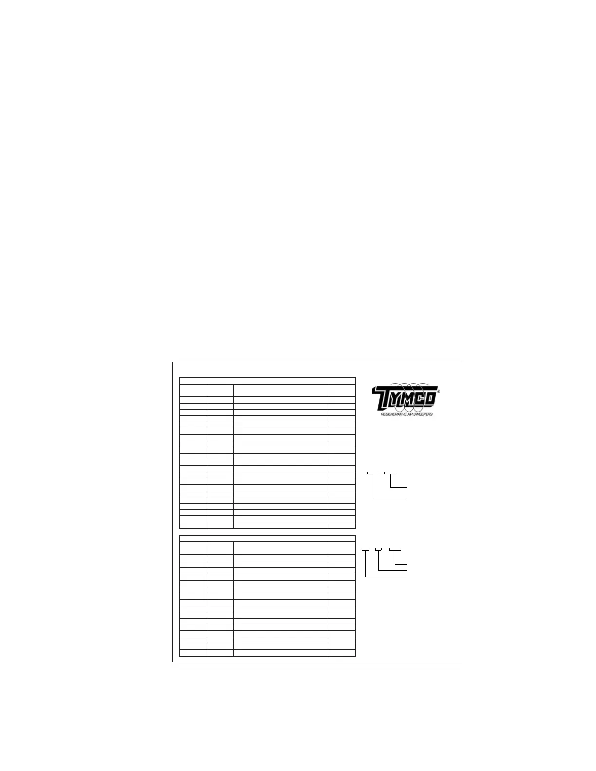
2019 45 D4OPTRS
The module has a custom program loaded on it to control the outputs based on module
inputs and CAN inputs. The program version, program revision level, and I/O information
are located on the Module LED/Wire Information Decal example shown above. The module
status, I/O, and program version/revision can also be viewed on the HMI display on the
control panel.
Module Input / Output LED Diagnostics
The control module has 12 inputs and 10 outputs. Each input and output has a corresponding
indicator LED located on the right side of the module in the status window. Most inputs are
switched by a high side or positive voltage signal. Some are switched by a low side or
grounded signal. When an input is switched, the corresponding input LED will illuminate
to indicate that the input circuit is closed. When the circuit is opened, the input LED will
turn off. All outputs switch to battery voltage (output 10 controls an optional circuit and can
reduce the output voltage with pulse width modulation). When the corresponding output LED
illuminates, the output closes the circuit to positive battery voltage supplying current to drive
solenoid, light, and other circuits.
Output Overload Protection & Power Fault Detection
The control module also has output overload protection and power fault detection. If any
of the module outputs overload due to a short circuit, the overloaded output will shut down
internally. The corresponding output LED will blink when the module commands the output to
turn on. This would indicate a shorted wire, solenoid, etc in that particular circuit. If there is
no bus bar voltage for a group of outputs, any output in that group that is commanded to turn
on will fl ash its corresponding LED indicating a power fault on that bus bar. Usually a power
fault on the bus bar is due to a blown bus bar fuse.
Module Network Diagnostics
The control module has a PWR and NET LED that indicate module power and network
communication status. The PWR LED will turn on when the module is powered up. It will
fl ash to indicate a system fault. The NET LED will turn on indicating it is communicating with
the network. If the NET LED turns off, this indicates the CAN datalink is disconnected from
the module.
J1-1E I1-1 IGNITION (+) R
J1-2A I1-2 PUH DOWN PRESSURE SWITCH (+) R-BK
J1-2C I1-3 AUX HYD REQUEST (+) O-W
J1-2F I1-4 LOW COOLANT (-) Y
J1-3B I1-5 REVERSE (+) BL
J1-3E I1-6 LOW WATER (-) W-O
v3.X
J2-1E I1-7 HOPPER LOAD INDICATOR (-) W
5021895
J2-1B I1-8 WATER IN FUEL INDICATOR (-) W-GR 508952
J2-2B I1-9 HYDRAULIC OIL TEMP SENSOR BR-W
J2-2D I1-10 OIL PRESSURE BR-Y
J2-2E I1-12 AIR FILTER RESTRICTION GY-R
J1-3C O1-1 RH GUTTER BROOM UP BR-W
J1-3D O1-2 LH GUTTER BROOM UP Y-BK
J2-1C O1-3 PICK-UP HEAD UP R-Y
J2-3C O1-4 SPARE Pin Location
J1-3F O1-5 WATER SYSTEM W
J1-1C O1-6 PICK-UP HEAD DOWN BK-W Plug Number
J1-1D O1-7 RH GUTTER BROOM DOWN GR-R
J1-1F O1-8 LH GUTTER BROOM DOWN W-BL
J2-3D O1-9 AUXILIARY HYDRAULICS RUN GY-BK
J2-1D O1-10 GUTTER BROOM SPEED R-GR
J1-1E I2-1 IGNITION (+) R
J1-2A I2-2 DOOR CLOSED PROX R-BK LED Number
J1-3B I2-5 CURTIAN LIFT SWITCH BL-O Module Number
J2-2B I2-9 PRECLEANER PRESSURE SENSOR BK-W Input/Output (I/O)
J2-2D I2-10 DST FILTER PRESSURE SENSOR BL-Y
J2-2C I2-11 AIR TANK PRESSURE SENSOR BR-R
J1-3C O2-1 TOP FILTER PULSE P-R
J1-3D O2-2 BOTTOM FILTER PULSE P-O
J2-1C O2-3 PULSE SYSTEM INDICATOR GR-O
J2-3C O2-4 SCAVENGE PULSE P-Y
J1-3F O2-5 DRAIN VALVE R-W
J1-1C O2-6 SENSOR POWER BR
J1-1D O2-7 CURTAIN LIFT UP O-BL
J1-1F O2-8 CURTAIN LIFT DOWN GY-R
J2-3D O2-9 FLUE ACTUATOR OPEN BK-R
J2-1D O2-10 FLUE ACTUATOR CLOSE P-W
FUNCTION
WIRE
COLOR
DST MODULE- VMM2
DST4 BlueLogic Module LED/Wire Information
PLUG #
PIN #
IN/OUT
LED
FUNCTION
WIRE
COLOR
SWEEPER MODULE - VMM1
X X - X X
J X - X X
Program Version #:
Decal Part #:
Module Part #:
IN/OUT
LED
PLUG # PIN #
PLUG #
PIN #
IN/OUT
LED
 Loading...